Home Blog Page 130

Inspiring Innovation

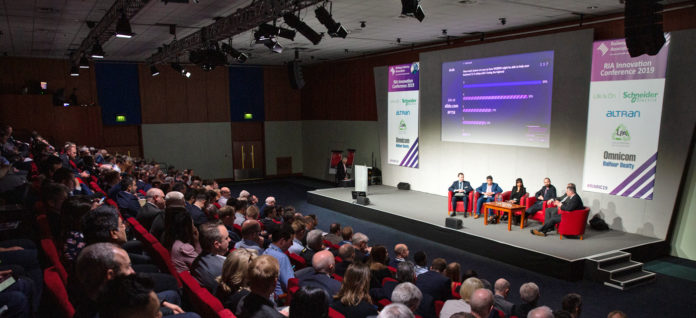
For ten years, the innovation conference run by the Railway Industry Association (RIA) has gone from strength to strength and, in 2018, won the Trade Association Forum’s best conference award. This year, it attracted a record 288 delegates and took place at Telford – a particularly appropriate venue as the town is named after the innovative civil engineer Thomas Telford and incorporates the UNESCO world heritage site of Ironbridge, which is considered to be the birthplace of the industrial revolution.

The conference’s mix of presentations, pitches, workshops, table sessions and an exhibition area has much to offer for anyone with an interest in how the rail industry can benefit from emerging technologies. It also provided useful guidance for companies that wish to develop their products for use in the industry.

Last month, Rail Engineer reported on how the conference addressed ways in which the rail industry could the reduce its carbon footprint, both from new technologies and further electrification, which RIA’s electrification cost challenge report shows can be delivered in an affordable manner. This month we feature other aspects of the conference.

Research opportunities

Opportunities to develop new technologies were the subject of presentations and workshops led by the UK Rail Research and Innovation Network (UKRRIN) and Network Rail.

Professor Clive Roberts of the University of Birmingham explained how UKRRIN was established in April 2018 after being awarded a £28 million Government grant with £64 million co-funding from various industry partners. Through effective collaborations between industry and academia, UKRRIN aims to provide a step-change in innovation to significantly improve UK rail performance by accelerating new technologies from research to market.

UKRRIN is led by the University of Birmingham, which also provide its digital centre of excellence. Other centres of excellence are for rolling stock (Universities of Huddersfield, Newcastle and Loughborough) and infrastructure (Universities of Southampton, Sheffield, Nottingham and Loughborough, and also Herriot-Watt University in Edinburgh). Testing facilities are provided by Network Rail, Transport for London and the Quinton rail technology centre.

Innovations already being developed by UKRRIN include verification of electrical clearances to reduce electrification bridge construction clearances (University of Southampton and Network Rail), in-vehicle acceleration data to detect track degradation (University of Huddersfield and Siemens) and Hydroflex, the UK’s first hydrogen train (University of Birmingham and Porterbrook).

Clive encouraged industry, particularly small-to-medium size enterprises (SMEs), to engage with UKRRIN’s centres of excellence. He acknowledged concerns about intellectual property rights and advised that this is retained by the company. He also advised that Universities can apply to become a new UKRRIN centre of excellence, partner or affiliate.

Network Rail’s CP6 research and development portfolio is a £357 million plan, of which £245 million is part of the CP6 settlement with the remainder to come from third-party funding. This is a 33 per cent increase on the CP5 settlement of £200 million plus £68 million third-party funding. However, the ORR requires this to be focused on Network Rail requirements rather than the more industry-wide requirements of the Rail Technical Strategy.

In addition, Network Rail has €39 million research funding over a seven-year period from Shift2Rail, Europe’s largest ever public-private research and development partnership. Despite Brexit, this funding is committed, although it is not clear whether there is be any future funding.

For CP6, Network Rail has five research programmes, as shown in the table. These are supplemented by the outputs from the Shift2Rail research programmes on trains, control systems, infrastructure, IT solutions and freight. Network Rail is also a client member of i3P – a platform for cross-infrastructure industry innovation that currently has 10 client organisations and 16 tier 1 contractors.

Network Rail Research programmes for CP6.

MADE pitches

As he opened the conference, RIA’s chief executive, Darren Caplan explained that its theme was “MADE in Britain” to reflect RIA’s focus on ‘Growing a sustainable rail industry in uncertain times’. MADE stands for Materials, Automation, Data and Energy, all of which are key areas requiring innovation. Later in the conference, companies were given the chance to promote such innovations in three-minutes pitches to the audience.

Examples of innovation in materials were Mott MacDonald’s use of a densified wood laminate to produce cost effective, low maintenance and visually sensitive overhead line structures; Dura Composites’ low maintenance, lightweight, modular GRP units that can be quickly laid on existing platforms to improve the platform train interface and the lightweight cable management sleeper produced by Oxford plastics which can be installed without disconnecting cables.

Automation in inventory management and delivery requests was stressed in Unipart Rail’s pitch for its SmartServe service, which guarantees supply availability. The automation of surveying featured in pitches by the Severn Partnership, on the use of Fugro rail-mounted laser scanners, and from Plowman Craven on using drones to conduct surveys, to an accuracy of 5mm, from which BIM models are produced and data handed over to asset owners.

Using data to precisely determine location was the subject of a pitch from Machines with Vision. This technique uses a ground-truth map which provides a unique fingerprint of the ground surface to determine an exact position. Using apps to collect and process data featured in presentations from Opinsta of a defect app for efficient maintenance reporting and from Bombardier on its goJoe app, which creates, gathers and processes data to generate passenger information.

Graffica’s pitch explained how, using its simulation platform, geographic and operation data can provide a virtual environment for capacity modelling and assessing the impact of various operational scenarios such as infrastructure and timetables changes. Fast in-train data transfer through a 10Gbit/s train ethernet backbone was described by LPA Connection Systems, which highlighted its copper ethernet switch.

An energy efficient, very light railcar was the subject of WMG’s pitch, which explained the concept of an innovative, lightweight diesel-battery hybrid power train with an 18-tonne tare mass that is able to carry 100 passengers at 100km/h. G-volution’s pitch offered reduced CO2 and particulate emissions from its dual-fuel technology, which also offers lower energy costs with the reduced cost of gas fuel and so can pay for itself in a few years.

Project innovation

HS2 chief executive Mark Thurston. (RIA)

HS2’s chief executive, Mark Thurston has no doubt that innovation is essential if HS2 is to provide the required service at an affordable cost. This particularly applies to project construction, when the project will be mobilising the supply chain at an unprecedented scale. Furthermore, productivity in the construction sector is poor. Figures from the office of national statistics show that construction output per worker is only 10 per cent greater than in 1997, compared with increases of 43 and 65 per cent for the production and manufacturing sectors.

Like Network Rail, HS2 is also a client member of the i3p infrastructure industry innovation platform, of which Mark is a co-chair. This was established in 2016 and is based on Crossrail’s innovation programme and has four strategic themes: digital transformation; manufacturing construction; life cycle performance and non-technology elements.

Mark stressed that innovation “has to be in the company’s DNA” and concerns people behaviours and collaboration. For this reason, HS2 is committed to early contractor involvement to integrate design development and construction planning from the start of the project. HS2 also has an innovation hub to collate and progress new ideas.

HS2 has also encouraged innovation through a ‘hackathon’ that produced innovations for smart infrastructure using augmented virtual reality, detecting employee fatigue and illness as well as enabling HS2 to be a good neighbour.

As well as construction innovations, HS2 is seeking new ideas to improve passenger experience, as described in features on HS2 trains in the last two issues of Rail Engineer. This includes the “step free from street to seat” requirement.

In a recently announced innovation, HS2 announced plans to heat 500 new homes near its Old Oak Common station to reduce their carbon footprint by more than a fifth. This is to be done by using air source heat pumps to convert warm air from the tunnel crossover box into hot water distributed to the homes through insulated pipes.

East-West Railway.

Another strategic rail link under development is East West Rail (EWR), which is creating a rail link between Oxford and Cambridge. Following the opening of phase 1 between Oxford and Bicester in 2015, phase 2 is currently being developed. This is the construction of 75 route-kilometres of new railway, to link Bicester, Aylesbury, Milton Keynes and Bedford, for which target costs must be submitted in May.

This is being delivered by the EWR Alliance which consists of Network Rail, Atkins, Laing O’Rourke and VolkerRail. Its director, Dominic Baldwin, explained how this is modelled on the collaborative Staffordshire alliance which constructed a new flyover at Norton Bridge. This engaged the supply chain at the early GRIP3 stage and functions as a single entity with risks and rewards equally shared. The aim is to create a highly motivated team focused on delivering value for money outcomes.

Alex Heward describes EWR innovations.

Alex Heward of Laing O’Rouke is the EWR alliance’s innovation manager. He has a dedicated budget and is supported by five innovation champions who promote innovation in accordance with the alliance’s structured process to encourage and develop new ideas. EWR has 30 needs statements for which solutions are sought. To date, this has resulted in 225 ideas submitted by the project team.

Examples of ‘innovations being progressed’ by EWR include shell abutments, which will save eight weeks in the programme and a 50 per cent reduction in site labour hours, fibre-reinforced footbridge decks increase lifespan by 25 per cent at no extra capital cost, and sleeper lateral resistance plates which save £45 per sleeper.

Alex advised that this innovative approach had saved £5 million to date and that EWR is keen to engage with the wider industry to disseminate its savings and learn of other industry initiatives. Although he stressed the importance of project innovation, it was accepted that this generally needs to be done at the early stages of the project, due to the risk from changes during project implementation.

Beyond the industry

RIA’s innovation conference always features thought-provoking innovative practice from outside the rail industry. This year was no exception, with presentations from the aerospace sector on an initiative to reduce software costs and timescales as well as one on innovation in the wider construction industry.

A presentation from Andrew Hawthorn from Altran and Mike Bennett from Rolls Royce described SECT-AIR (Software Engineering Costs and Timescales – Aerospace Initiative for Reduction) which is a £10 million project, part-funded (50 per cent) by Innovate UK. It is a pan-industry initiative which involves ten aerospace companies, of which Rolls Royce is the lead participant, together with the universities of Oxford, York and Southampton.

SECT-AIR aims to significantly reduce rising software development costs and timescales that dominate the development costs of new products which, if not addressed, will result in unacceptable delays introducing new products, especially as Rolls Royce is currently developing multiple new engines.

As an example of costs, the software for an engine control unit typically has 300,000 lines of code at a cost of about £100 per line. One such engine is the Ultrafan which, unlike the Trent engine it will replace, will have a power gearbox to control fan speed, which is anticipated to have double the electronics and software. Its planned introduction from 2025 may be at risk unless software development timescales can be reduced.

SECT-AIR aims to exploit world-leading research to improve the software design, production and the verification process, the later accounting for most of the time and cost. Solutions include avoiding rework through better systems specification, improved handover between stages and automated verification. No doubt this initiative will offer valuable lessons for the rail industry.

Software is also an important aspect of innovation in the more traditional construction industry which, as Mark Thurston noted, doesn’t have a good productivity record. In his presentation, Peter Kirk, managing director specialist services at Balfour Beatty, explained what his company is doing to change this. Before doing so, he emphasised the importance of first getting the basics right, including effective communication and fostering a culture of trust and collaboration.

In developing innovations, Balfour Beatty considers what is needed now, in the near and in the far future, to which it devotes roughly 70, 20 and 10 per cent of its efforts. The company’s aim is to introduce new technologies to reduce workforce site time by 25 per cent by 2025. This includes 4D planning, artificial intelligence (AI) and industrialised construction.

The planning and constructability benefits of a 4D BIM model were evident from the model shown of the five-year London City Airport development programme, which provided detailed 3D views of the numerous construction stages throughout this programme.

An example of this in the rail industry is the use of AI to train the pattern-recognition software that is used to detect track defects from numerous photographs which are taken at high speed by the New Measurement Train. In recent trials, using AI in this way has significantly reduced the number of false positives.

ElecLink – a 1GW electrical interconnector between the United Kingdom and France via the Channel Tunnel.

In contrast, a good example of the industrialisation of construction is the provision of a one-gigawatt high-voltage direct-current interconnector in the Channel Tunnel, the world’s first such installation in a live rail tunnel environment. The project uses numerous off-site and near-site techniques, the most impressive being a specially built 500-metre works train to enable the installation of twin 320kV cables in the five-hour working window per week where access is available.

Peter is certain that such innovations must be the future of construction. However, he cautioned that the need to upskill and develop staff for such innovations should not be under estimated. He finished his presentation with a futurist video of a human free construction site in 2050, where people instead plan and support construction from safe environments. Whether this will be the future remains to be seen. Peter’s view is that, although it’s not possible to foresee the future, it is important to have a vision and work towards it.

Keynotes

As well as presentations on specific issues, keynote presentations emphasised key points and made it clear what had to be achieved.

Valerie Layan, Schneider Electric’s transportation segment president, reminded those present that they were now in the fourth industrial revolution, as artificial intelligence changes industrial operations. The increasing use of technologies such as robotics, autonomous vehicles and quantum computing is driven by huge amounts of interconnected complex data.

As an illustration of the exponential growth of data, global internet traffic in 1997, 2007 and 2017 was respectively 60 petabytes (1015), 54 exobytes (1018) and 1.1 zetabytes (1024). Valerie advised that less than ten per cent of data is currently used.

She noted that digitisation accelerates business disruption, giving examples of how Uber and Netflix provide more responsive, less expensive services than their predecessors. Rail businesses needed to be aware of both the threats and opportunities from the fourth industrial revolution. In respect of benefits, Valerie considered that rail businesses should be able to reduce energy costs by 25 per cent through smart energy management, increase operational efficiency by 20 per cent using big data, and reduce ownership cost by 15 per cent through condition-based maintenance and targeted life extension.

Transport for London’s (TfL) head of transport systems engineering Claire Porter explained how TfL intended to use emerging technologies to deliver innovative solutions to support the Mayor’s transport strategy. This has three aspects, which are:

Healthy streets and healthy people with targets of 20 minutes active travel per person by 2041, three million fewer daily car trips by 2041 and zero emissions by 2050;

A good public transport experience including better use of the Thames, improving bus speeds by 10-15 per cent and reducing rail and underground overcrowding by 10-20 per cent;

New homes and jobs with high density, mixed use places in well-connected locations.

She reflected that the first aspect was particularly important, as 2,000 people a year are killed on London’s roads and a recent report had estimated that the capital’s poor air quality results in 9,000 deaths a year.

To deliver the engineering support for this strategy, TfL has recently amalgamated its 1,500 engineers into one organisation that centralises support for such things as safety, telecoms and infrastructure, with dedicated systems support for vehicles, power, track and road & rail traffic control systems.

To promote innovation, TfL has its own innovation portal, open both to employees and members of the public. In partnership with the London Transport museum, its Innovate TfL programme encourages innovation by engaging with a diverse population at an early age to ask them for innovative solutions to a real TfL challenge.

TfL is also following Network Rail’s practice of producing challenge statements and now has a standards-challenge process, which RIA helped to develop.

Network Rail chief executive Andrew Haines. (RIA)

Network Rail’s new chief executive Andrew Haines is clear that the company must change. It has lost trust and is insufficiently responsive to its customers. Asset performance must improve, product approval is too slow and, although projects have delivered good infrastructure, passengers have suffered as this was not linked to train plans.

He recognised that, all too often, such people find themselves frustrated by the structure and processes that stop them doing a good job. Often, collaborative working only happens because people put a lot of what the company tells them to do to one side and find a better way of doing things for themselves.

For these reasons the company must change and reorganise so that it is closer to its customers.

Network Rail must also innovate, so it is encouraging early contractor involvement and challenges to standards. It is also devolving its research programme, which in the past had been too-centrally led. Andrew expects technology to be introduced quickly, but considers that clarity on best practice is required. He also wanted the industry to respond with solutions to Network Rail’s challenge statements.

RIA’s innovation conference certainly offered solutions, although these need to be matched to business need. As always, this was a stimulating event with a good mix of formal conference activities and informal networking that is worthy of its Conference of the Year accolade. Definitely a date for the diary next year, when the conference will move to June – keep an eye on the RIA website for more details.

Single Line Internet Control

The safe operation and signalling of single-line railways are crucial as any head-on crash between two trains is potentially catastrophic. Incidents of this nature are thankfully very rare as the systems devised to allow only one train into a single-line section are robust and well respected.

Train drivers have to be assured, beyond any doubt, that it is safe to proceed into the section ahead. Initially this was achieved by possession of a single physical ‘staff’ for the section, later developed into tablet or token machines to give more flexibility. In more modern times, No Signalman Key Token (NSKT) operation has emerged, whereby the drivers actually operate the token machines, mainly at passing loops, instead of a signaller.

Tokenless Block is another alternative, where track circuits give signallers full viewing of the single line section to clear the signals accordingly. Use of radio in the RETB (Radio Electronic Token Block) application has also been developed.

Tablet or token machines require a landline connection between adjacent signal boxes, never a problem in the past but it can be a constraint nowadays, with the continuing demand to rationalise lineside infrastructure. So, can other means be used to connect the token instruments?

Park Signalling, now a member of the Unipart Rail group, has developed a system whereby secure IP (Internet Protocol) communication is used for the connection, either over the internet or any other non-dedicated communications link such as 4G cellular radio or Network Rail Telecom’s FTNx network. This represents an innovative means of adapting 21st century technology to link with Victorian engineering.

Rail Engineer went to the Ecclesbourne Valley railway at Duffield to view a demonstration of the system.

Tyer token machine

The Tyer token machine

To understand the operation, it is necessary to know how a traditional token machine works. It has five basic components – a plunger (1) for transmitting bell signals to adjacent instruments, a pointer (2) for indicating to the signallers the state of the token section, an indicator (3) to show the outgoing and incoming signals sent via the plunger on the machines at each end of the section, and a commutator (4) in which the tokens are inserted when taken out or put back into the magazine (5) for holding the tokens.

Operation consists of the signaller at one end sending a bell code to the signaller at the far end. If the section is clear, the far end signaller keeps the plunger depressed whilst the near end signaller slides a token up from the magazine and into the commutator, turning the token anti-clockwise to remove it from the machine. The commutator turn reverses the line polarity to the far end machine which electrically prevents a token being removed from that machine or from removing a further token from the originating machine.

The token is put into a leather pouch and handed to the driver who checks that it is correct for the section ahead. Once the train has reached the far end, the driver hands the token to the signaller who puts it into the commutator turning it clockwise, which then allows the instruments to be back ‘in phase’ in readiness for the next token extraction.

In short, only one token can be removed at any one time for the particular single line section.

DiBloC – Digital Block Controller

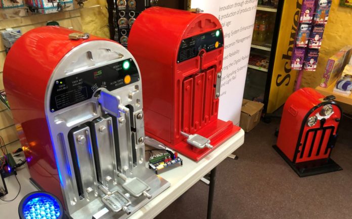
This is the fancy name for the almost lookalike new token instrument. In designing the machine, Park Signalling took a fresh look at some of the features in the old unit to decide whether they were still required. As such, the operation is similar but not identical to what has gone before.

DiBloC – Digital Block Controller

The shape and size of the machine is the same, including the magazine for holding the tokens, but is now made in aluminium. The front panel is slightly different in both facilities and operation. The bell plunger and the pointer for indicating the token state are replaced by an illuminated push button for ‘Request Token’, a ‘Signallers Release’ button/light for when permission is given for a token to be extracted, plus two LED lights to indicate ‘Token Available’ and ‘Token Not Available’.

The commutator is similar but its position is read optically to interface with the electronics that lock or unlock the insertion or removal of a token. Insertion of a token is not dependent on power being available. The token key ‘cut’ is compatible with any existing tokens and any replacement project can retain the original tokens, thus providing the traditional safeguard against trying to insert the ‘wrong’ token into the machine.

Completing the front panel are a series of LEDs to indicate power failure, network fault, building intrusion and suchlike.

Behind the front plate is a printed circuit board with duplicated processors and electronics that control the instrument, including the mechanical aspects and electrical shotbolts. This is linked via a multiway cable to an internet router which, at Ecclesbourne, was located in an equipment cabinet underneath the token instrument but could be at any convenient office location. This router is not unique to the machine and may provide the internet connection to other computer equipment at the location.

The IP (Internet Protocol) address is assigned a static identity and provides a single network channel. For resilience purposes, two fully independent network channels should be made available to guard against one channel failing. The power is 24V DC and can incorporate an uninterruptable power supply (UPS) back-up battery if required. The weight of the unit is around 27kg.

The connection from the router to the outside world can be either by fibre, 4G cellular network, satellite or to a rail company’s own telecom network. The system is designed to allow up to six token machines in a group. This will cater for situations where, for instance, a terminus location may have a machine on two or more platform ends or where an intermediate machine may be required to lock a train into a siding or freight yard and the token given up.

The IP arrangements will be similar to creating a group address list with messages being sent in a loop from machine 1 to the next machine and so on until the last one sends it back to machine 1.

DiBloC in operation

The system can work in various modes:

  • Signalbox to signalbox, where two signallers extract and return the tokens;
  • Signalling centre to other locations (typically passing loops) where the driver will activate the token machine;
  • ‘No Signaller’ operation with drivers operating the machines, located normally at passing loops, akin to NSKT operation.

To extract a token, firstly the ‘Token Available’ green LED must be lit and the ‘Request Token’ button is pushed. This sends a communication to all the other machines in the group and, if no token is already out, the machine indicates that a token can be released. The token is then lifted from the magazine and rotated out of the commutator. All the machines in the group will then be informed that a token has been extracted and the red LED ‘Token not Available’ is lit.

Once the driver has checked that the token is correct for the section ahead, the train can proceed.

At the far end, the token is inserted into the commutator and turned, with the optical reader recognising that a token replacement is occurring, thus sending an internet message to the other machines that a normal state has resumed and the ‘Token Available’ LED is again lit.

Where a form of centralised signalling control is in operation, the driver who requires a token presses the ‘Request Token’ as before, but this sends an internet message to the signal centre. If the signaller is in agreement to a token being released, they will press the ‘Signallers Release’ yellow button, which will initiate an internet message to the requesting token machine where an audible alert will sound, indicating that the request has been granted and the driver can now extract the token. Such a situation will exist where train regulation and timetable adherence is such that a train may be held at a location whilst another train is allowed into the section first.

In the UK, the operating rules require that verbal permission from the signaller is obtained before any token extraction takes place so that both parties understand the requirement of that particular train movement. In other countries, where the overall route management is less formalised, it is possible that a ‘first come, first served’ token extraction will be allowed, although this can cause timetabling problems if trains are running late.

Commercial considerations

The concept was initiated by a Park Signalling engineer who also worked as a volunteer on a heritage railway and recognised the problems of providing traditional telecom line connections. Many heritage lines use traditional token instruments and Network Rail still has around 110 token machines in service. There are also many countries in the world that have been sold Tyer token machines down the years and where maintaining reliable lineside cabling is a challenge.

The market is not huge but is considered worthwhile to make the development investment, which was supported by the Birmingham Centre for Railway Research and Education.

The first application will be on the Ecclesbourne Valley line, where the staff can test and evaluate the system and tease out any weaknesses. A second application may well be at the southern end of the Central Wales line (Shrewsbury to Llanelli) where NSKT operation is the mode of operation.

Reaction to date is encouraging but with some potential users asking if the bell push plunger and the ‘train going or train coming’ indicator can be incorporated. The answer is yes, but it will have cost implications and the modification would likely be bolt-on units. Users are asked to consider whether, in these days of cellular telephony, such add-ons are really necessary.

Clearly, the machines are precision made and the design has incurred development costs, so investment is required when replacing existing units. Park Signalling is mindful of this and will offer various hire purchase or rental options, as well as an installation service which can include maintenance and fault finding. An arrangement with SigNet Solutions at Derby can give training to prospective users.

The system incorporates SIL 3 safety functions and is designed to EN 50126, 50128 and 50129 standards with certification expected shortly. Network Rail guidelines for cyber security are followed.


Thanks to Ian Allison, Robin Lee and the engineers at Park Signalling for a most interesting day.

Points of no return

Those of us who now need afternoon naps can find the modern world baffling, so it’s good to know that some things endure despite apparently passing their sell-by dates. And I include myself in that. Waving chequered flags to warn those in the four-foot that their lives are endangered by an approaching train spans three centuries and, even on the East Coast main line, you can still find surveying teams using lengths of string to measure curvature. Simple and effective was a global preference before ones and noughts came along.

The pace of technological change over the past 20 years has been breathless but hugely enriching. That said, change can bring consequences nobody envisioned – fires that need to be fought. So, there’s an understandable tendency to take a risk-averse approach when it comes to innovation in safety-critical environments. But, if we’re to benefit from the opportunities it presents, we have to recognise and embrace the associated challenges.

Coming together

A generation of railway surveyors will never have held string, electronics mostly superseding it over the past couple of decades. As with everything, the capabilities of today’s instruments continue to improve over time. Most share common technologies – inertial measurement units, satellite positioning, laser scanning, photogrammetry – and capture essentially the same things: Easting, Northing, Elevation (x, y, z), perhaps Intensity (distinguishing between different materials) and Red, Green, Blue values. But, to maximise commercial interests, developers often employ proprietary software to process data and translate it into something useful for the engineer.

The railway, of course, comprises many disciplines – signalling, drainage, OLE, renewals – all seeking data for different design or construction requirements, using different methodologies at different levels of detail. So, there’s clear potential for inefficiencies and additional workforce risk through repeat visits to the same place.

Those realities are amongst the drivers of a project being led by Network Rail’s Signalling Innovations Group (SIG). During CP6, it intends to grow the survey and design tools it’s helped to develop, alongside which it will undertake research into the most effective ways of integrating survey data from multiple sources, as well as the complex influencing factors. The hope is to reduce the requirement to venture on or near the line.

SIG’s ambition is for a variety of surveys to be made available via a central open-source repository which everyone can tap into, although there is a recognition that it’s just not practical to have every possible survey type for every location, all gathered under consistent conditions. At the same time, an obvious fundamental requirement is that the extremely high levels of quality and accuracy needed for future automated design cannot be compromised. Dealing with this latter issue demands a much deeper understanding about the various methods of data capture.

Stitch and blend

To establish comparable data sets from a variety of techniques, SIG needed to set up a baseline survey test site away from Network Rail’s main line infrastructure. Initially, the company’s test tracks at either Melton or Tuxford seemed the ideal location, but constraints arising from their successful full-time role for train testing meant that it was instead decided to approach one of the country’s heritage railways.

An agreement was reached with the Midland Railway Centre at Butterley, Derbyshire, delivering a welcome financial boost to an attraction celebrating its 50th anniversary in 2019. At Swanwick Junction station, Bridgeway installed 15 control points through a 200-metre-long double-track section, amidst S&C, signal posts, platform furniture and the like.

“The facility gives us the opportunity to carry out multiple surveys within a narrow time window,” says Natasha Purewal, Network Rail’s scheme project manager, “minimising differences in factors such as weather, lighting and the presence of transient objects.”

The first event took place in mid-March, attended by four suppliers using manual trolley-based equipment, a rail vehicle-mounted system and an Unmanned Aerial Vehicle, otherwise known as a drone. Let’s make the point now that it is not Network Rail’s intention to identify a preference for one technique or product over another, and what follows here is not a sales pitch.

Devil in the detail

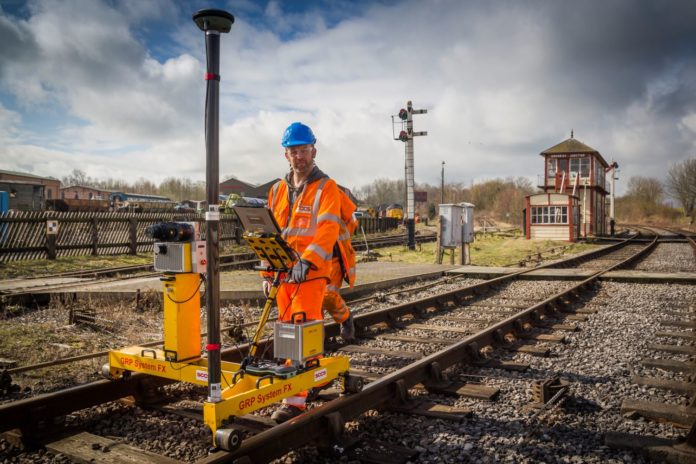
SCCS and Korec both demonstrated trolley-based kit, respectively using the Amberg IMS 5000 GPS system and the Trimble GEDO CE.

In their basic forms, these use an inertial measurement unit (IMU) – a device comprising gyroscopes and accelerometers – to measure cant and gauge as they are pushed along the track. But that only creates a relative model hanging in space; by recording GPS/GNSS coordinates alongside it, the IMU trace can be accurately transposed onto a real-world SnakeGrid.

The addition of a 360º laser scanner enables a 3D point cloud to be mapped of the trackside environment, extending out to the boundary fence. The scanners spin up to 200 times per second, collecting around 1,000,000 points.

Although control points are captured as a matter of routine, Amberg and Trimble’s trolley-based systems don’t need control points and can therefore provide a continuous measurement of track conditions, such as twist faults. Typically covering two miles in an hour, the process is quicker than conventional fixed surveying techniques and, by reducing the number of people involved, represents a means of gathering large amounts of data whilst minimising workforce exposure to on-track risks.

Critically, what this approach offers is high resolution. “At walking pace, we’ll have a laser profile every 5mm,” says Dave Dampier from SCCS, “so you’ll easily find the centre of a target; and the same goes for a feature such as a catchpit or a signal post.”

“What’s important is to have an understanding of the accuracy of all the different coordinate systems,” asserts Korec’s Matt Lock, “because that determines whether you can use the data for an engineering application or whether it’s more of an asset registry.”

Fast track

Mounted to a specially-equipped Class 37 locomotive, provided by Colas, was a portable mobile mapping unit from Balfour Beatty Technical Services, known as OmniCapture3D.

The key advantage of this kit is the ability to quickly survey an entire route – comfortably covering more than 100 miles in a day – with little or no impact on traffic. There is no need for possessions and no boots on the ground, except at the depot when the equipment is being commissioned or decommissioned.

On the Class 37, the system can gather data at 70mph, although speed does have the effect of reducing point density and it therefore offers less detail than a trolley-based system. To help infill gaps or ‘shadows’, two offset Z+F Profilers are used, angled towards each running rail. Again, these can capture one million points in 200 profiles every second – effectively one profile every 80mm or so – and are fully synchronised to IMU and GPS units, as well as a tachograph.

There’s also an imaging device to provide additional context, delivering 4K, high definition, infrared or spherical views.

“It’s certainly appropriate for feasibility studies and the accuracy we’re going to now gets us to a higher level of detail, so you can go on to do your design with it,” says John Garlick, Balfour Beatty’s measurement services manager.

Eye in the sky

In principle, the approaches described so far gather three-dimensional data from a radial viewpoint above the four-foot, moving only in one dimension; as a result, nothing is seen beyond the first obstruction encountered by the laser. However, the advent of unmanned aerial vehicles (UAVs) has revealed alternative perspectives from which both plan and elevation views can be derived.

Bridgeway Aerial showed off a DJI Matrice 210, one of several aircraft operated by the company for inspections, photography, 3D modelling and LIDAR applications. They are capable of acquiring geospatial data that would previously have been impossible to secure.

In the case of a structure, a series of high-resolution photos and associated GPS coordinates are taken from strategically-defined positions – including upward views into ‘hidden’ elements such as arch soffits – and stitched together using photogrammetry software. An orthomosaic representation is then extracted (that’s the task of correcting geometrical errors caused by topographic relief, lens distortion and camera tilt) and, from this, a geo-referenced three-dimensional point cloud is processed. It’s even possible to produce a physical model of the structure using a 3D printer.

The data points have a position relative to each other derived from the UAV’s GPS system which, at any one time, achieves its accuracy by typically connecting to around 18 satellites. But, to obtain an absolute position, the cloud is tied to trackside control points by manually identifying them at pixel level on the photographs.

The resolution is determined by the requirements of the brief and defines the speed at which the survey is undertaken. Paul MacMahon, senior UAV pilot, explained: “For an accuracy of ±20mm, we fly quite slowly – perhaps three metres per second – and gather several hundred pictures. It will also depend on weather conditions – how the UAV is performing on the day.”

Horses for courses

All these devices currently play unique and valuable roles in their own right, having proven themselves to fit within the parameters and constraints of rail. Whilst the technology will doubtless evolve, the consistent challenge will be to fulfil the client’s requirements and ensure data quality compliant with appropriate standards.

“At the moment we have bandings that each system is signed-off against,” says Wayne Cherry, Network Rail’s senior innovations engineer. “We’re now trying to get everything to a level that provides seamless integration, to give us confidence within our own disciplines and throughout the industry – supporting the principle of ‘survey once, use many times’.”

The presence of four key suppliers at the Butterley test site indicates a willingness to engage and collaborate in realising the Signalling Innovations Group’s stated ambitions. There are commercial and safety imperatives that they are clearly buying into. A workshop is being held where the companies will present the information captured on the day – initially demonstrating the capabilities of their own software – before delivering the data in an open format for manipulation by SIG into a single model.

Going into CP6, there is a recognition that, at times, the railway is capturing too much duplicate data across the various disciplines and is not always being clever enough about what to do with it. This project shows an emerging commitment to adopt a much more coordinated approach.

Whiteball Tunnel

Now fit for purpose in the 22nd century

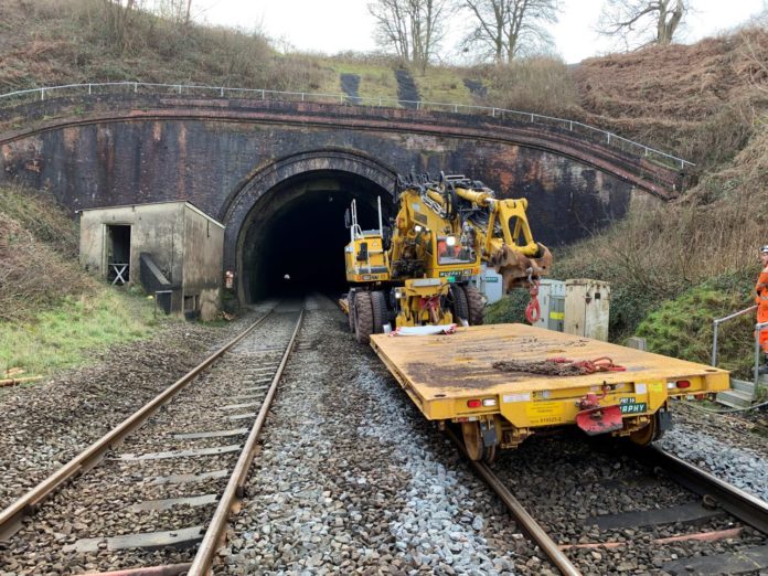
Railway passengers planning journeys earlier this year to and from the south west between Monday 18 February and Friday 8 March 2019 were being urged to check before travelling, owing to essential maintenance work that took place at the 1,000-metre long Whiteball tunnel near Tiverton Parkway in Somerset.

Rail Engineer readers with good memories will recall that the work in Whiteball Tunnel is linked to a project which started in 2011, when preparatory work was carried out in the tunnel. The preparatory work caused little disruption to trains but was the launch of a multi-staged plan to significantly improve the state of the old brick lining throughout the tunnel.

The tunnel, named after the nearby village of White Ball, was built by Brunel. The 1,000-metre-long Victorian brick-arch structure, opened in 1844, straddles the Somerset/Devon border. It provides a path for trains to travel under the white sandstone of the Blackdown Hills located between Taunton and Exeter.

Sulphurous steam trains

The clay used for the millions of bricks used for the tunnel lining came from local pits. The engineering bricks produced were of a good quality but, over the years, weathering, chemical reaction from the sulphurous steam trains, voiding behind the brick lining and the degradation of the mortar joints, has meant that there has been a rolling programme of repairs to the lining throughout most of the 20th century, right up to the present day.

Following on from the work carried out in 2011, a similar three-week closure of this route took place in 2014. This enabled this stage of the programme of work in Whiteball Tunnel to take place.

The structure gauge within Whiteball tunnel is very generous, due to Brunel’s ‘broad’ track gauge of 2,140mm. As a consequence, past generations of engineers have been able to carry out substantial repairs, turning new brick arch rings within the existing lining using shields to support the brickwork and workers during construction.

These shields, usually made out of old bullhead rail, were designed to match the profile of the tunnel and they could be clamped together to accommodate the varying lengths of the tunnel that needed repairing. The arch ring structure also included a staging platform at a level that allows trains to run underneath. Over time, these rings were left in situ, forming a permanent feature within the tunnel.

Unhealthy and hazardous working environment

The shields were placed over concrete strip foundations designed to match the length of arch required to be turned. Once in place, skilled bricklaying teams constructed a two-brick arch inside the existing lining. The process was very effective, but also very time consuming and expensive. It required a highly skilled workforce, which had to endure difficult circumstances, working at height in an often very uncomfortable and unhealthy environment.

This hostile environment, coupled with the accelerating deterioration of the tunnel lining, is the reason why Network Rail decided to change its strategy and adopt the Ram Arch System which is in use in the tunnels on London Underground.

A different approach

The Ram Arch System consists of easy to handle, two-metre lengths of galvanised steel mesh. These are bolted together on site to form arch rings one metre wide that are then interlocked and supported on slotted angle brackets fixed into the brick lining about two metres from the cess level. Each ring is secured to the brick lining using two 200mm long, temporary dowels, fixed with a five-second “resin hit”.

Once everything is in place and secure, a more permanent fixing is introduced. The temporary dowels are replaced with five permanent rock anchors that are fixed with a 10-second “resin hit” for each individual arch ring. Finally, spine wires are threaded along the profile of the arch to link the individual arch rings together and provide additional stiffness. These spine wires are then fixed to the now continuous arch structure using a pneumatic Hog Ring Gun.

Once the rock anchors are in place and the spine wires fixed, the nuts on the rock anchors are loosened to create a 2 to 3mm gap between the new galvanised arches and the existing brick lining. This is the work Network Rail completed in 2011 and 2014, which formed Stages 1 and 2 of the project.

In situ or precast?

The work undertaken this year, Stage 3, includes the installation of 1,500 “Butterfly” dowels, spaced 50cm apart, fixed into the side walls of the tunnel following six areas within the tunnel where the Ram Arch system has been installed.

The original plan was to fix precast concrete slabs to the sidewalls of the tunnel to underpin the Ram Arches. However, this was considered too complex, given the irregularities within the tunnel and the length of possessions required to install the units. The dowels were fixed by a two-man team working with a trolley. It was a simple and effective approach and, most importantly, it was carried out without impacting on the train service.

Having installed the dowels, the work carried out during the three-week closure was now ready to start. The principal contractor for Stage 3 was Murphy, with BEDI Consulting undertaking the design work. The work involved spraying ‘shotcrete’ concrete to the profile of the tunnel throughout the repaired areas.

Scott Pillinger, Network Rail’s programme manager for this work, outlined the logistics involved in completing this task and they were challenging, to say the least.

The logistical challenge

The first challenge was the location of the site. The closest access to the tunnel is one mile away from the Taunton end portal and access to it was down narrow, winding country lanes. Throughout the three weeks, two twelve-hour shifts, with 50 or more operatives on each shift, would be working and lodging in the vicinity. Appropriate facilities were required both on the site and within the tunnel throughout the work period.

In addition, as in any tunnel environment, everything has to work in a linear fashion so that what goes in must not hinder what is coming out, and vice versa. But that’s just the easy bit, which most good contractors will deal with almost as a matter of course.

The real challenge was to shotcrete (spray concrete) the tunnel lining throughout the 355-metre length of repair which was, in fact, made up of six different locations in the tunnel. The plan was to spray the concrete in two-metre strips working from the cess to the crown and back down to the other cess. Scott explained that the first week was not as successful as they had hoped but that the second and third week were very productive.

Two robots, ‘Ivy’ and ‘Holly’, carried out the spraying but, to ensure that safety was not compromised, only one could be used in the tunnel at any one time. Each robot was rail mounted with outriggers and was operated by a ‘nozzle man’ standing close by, using a remote control.

Monitoring the sprayed lining

To ensure the quality of spray thickness was maintained, a surveyor was located about 10 metres away. He was in constant communication with the nozzle man and, using a point cloud laser survey, he was able to confirm the depth of the concrete being sprayed. The aim was for a constant 150mm depth throughout the tunnel profile.

While this operation was underway, concrete was being continually transported to site using a rail-mounted concrete mixer to feed the robot. Because of the special design of the shotcrete, with its carefully designed fibre content, the nearest plant capable of providing the quality and quantity required was based in Derby. To keep the site productive, each shift needed up to 60 cubic metres of shotcrete concrete. Murphy had erected eight silos at the main site with a total storage capacity of only 40 cubic metres. Therefore, deliveries from Derby to site had to be reliable and very regular.

A concrete mixer holds about five cubic metres, so it is not necessary to go into any more detail to emphasise how critical it was that every aspect of this project had to work effectively and efficiently. That includes allowing for the vagaries of the somewhat-unpredictable motorway system. The concrete was transferred to smaller wagons on reaching Bristol and, to ensure that there was a continuous flow, wagons were held at strategic locations en route. The narrow lanes close to the site were, according to Scott, “the cleanest in the county”, helping to minimise disruption to the local community.

Review of the ‘bounce back’

All went well and the work was completed on time. However, the team identified that the ‘bounce back’ of sprayed concrete, calculated to be about 20 per cent maximum at design stage, was actually closer to 30 per cent. The track had been protected throughout using boarding and plastic sheeting, so there was no risk of the track ballast being contaminated, but this was obviously a concern and detailed analysis of the whole process is now underway to better understand the reasons why this happened.

Outstanding safety record

The result of this work is that Whiteball tunnel is now a safer space. A significant length of spalling brickwork is now protected. The ingress of water is managed and channelled into the tunnel drainage system and the drainage system itself has subsequently been overhauled and renewed.

Scott was eager to point out that Murphy performed to a very high standard ensuring, that the nail biting ‘just in time’ logistics worked effectively.

As always, a good indicator of a well-run project is its safety record. Throughout the work, over 400 ‘close call’ issues were raised, highlighting the level of care and ownership that existed on this site, and, with well over 20,000 hours worked over the 19 days of the blockade, only one incident was recorded, when someone slipped on some steps but did not incur any injury.

What is most exciting is that this work is testing and pushing the boundaries of engineering maintenance in tunnels to ensure that Network Rail’s significant stock of operational tunnels in the UK will be fit for purpose well into the 22nd century.

White Hart Lane

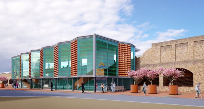
The facades of the new building will refl ect the Lea Valley’s horticultural heritage, with terracotta pot and louvred glass panels.

A new station for a new stadium

White Hart Lane is the station for, and shares its name with, Tottenham Hotspur Stadium. It is used by 1.3 million customers each year, with a daily peak usage of 1,446, rising on match days to 7,455. This is expected to increase to 12,395 next season, now the new 62,000 seat stadium has fully opened.

Abellio Greater Anglia and London Overground, which took over some of the former’s services in 2015, both serve White Hart Lane station. The existing station and tracks are located on an embankment, with the platforms carried on narrow brick-arch viaducts built into the earthworks, a form of construction common in this area.

The High Road West regeneration area, with White Hart Lane station at the western end.

The High Road West Masterplan

White Hart Lane station is located on the western end of London Borough of Haringey’s ambitious ‘High Road West’ regeneration masterplan. The area between the station and Northumberland Road station to the east includes a 1950/60 development that is to be redeveloped providing 2,000 new homes, along with retail and public spaces around the rebuilt stadium.

In 2014, Haringey engaged Landolt + Brown and Arup to draft the masterplan. This envisaged creating a new public space between the stadium and the station, with ‘Moselle Square’ replacing the aged flats of the Love Lane estate. A key part of this would be an enlarged, and architecturally engaging, station at the end of this boulevard, forming a key gateway to the regenerated High Road West area.

The masterplan was generally well received in public consultation and it was agreed that the station redevelopment should go ahead.

Delivering the project

The project is being led by Transport for London (TfL), with regular engagement with representatives from London Borough of Haringey and the Greater London Authority (GLA). Funding is being provided by TfL’s Growth Fund and GLA Mayor’s Regeneration Fund.

Taylor Woodrow was awarded the £17.8 million contract to redevelop the station, delivering improvements including a new ticket hall, station entrance and step-free access from street to platform.

The existing station is of a poor standard, offering very limited passenger facilities and no step-free access. There are single staircases to each platform that struggle to cope on match days, with no alternatives in case of an emergency.

The surrounding area of lockup garages and land was in a poor state of repair and had been identified as a hotspot for anti-social behaviour and criminal activity. It was recognised that the redevelopment of the High Street West area, and of the White Hart Lane stadium, would place tremendous additional footfall pressure on the station. The footway beneath the underbridge was relatively narrow and discouraged pedestrian movement between the two sides of the line.

The White Hart Lane station upgrade aims to rectify these shortcomings by creating a new western station entrance on Penshurst Road and a new ticket hall south of the current station building on Love Lane. This would be at a more central location along the platforms, facing across the future Moselle Square with urban realm works to the station forecourt and surrounding area.

Lifts will provide step-free access from the street to platform level and two new stair accesses from the new ticket hall will reduce bottlenecks and speed up the movement of passengers on match days. The existing stairs will be retained as emergency evacuation routes.

The new station is designed to cope with and manage the heavy footfall of match days, including a control room for British Transport Police. The two sides of the station will be connected by a new underpass and a second public underpass will provide a new and better public pedestrian route from east to west.

The architectural design for the station was carried out by Fereday Pollard, building on Landolt + Brown’s concept design. The external façade of the two entrances include terracotta pot panels, reflecting the area’s history of manufacturing pots for the Lea Valley’s market gardening industry, as well as louvred glass, drawing local inspiration from its horticultural glasshouses.

Spile tubes were driven through the embankment by a Bohrtec BM 400 auger rig, working from a temporary RMD platform on the west side.

Underpass construction

The design and construction of the works was technically complex and was explained to Rail Engineer by Taylor Woodrow’s Paulo Lotter and Tony Gee’s Oliver Engleback. The structural engineering design by Tony Gee and Partners was complex for a small site but reflected the challenges of the original structures and earthworks.

The original concept for the passenger and public access through the embankment was to have been a new bridge constructed top down, however this would have required multiple weekend closures. Taylor Woodrow’s alternative design of twin underpasses, using 9m x 3.6m x 4.7m jacked boxes installed during a 52-hour possession, was instead selected by TfL.

The precast boxes would be a tight fit into the existing structures, with their formation below that of the viaducts’ piers and with only 75mm clearance to each side. There would also be only 1000mm clearance below sleepers, which could be a very great risk to track stability, resulting in a spile canopy (an array or ‘canopy’ of self-drilling rods or ‘spiles’ driven into the roof above the subway to prevent ground movement) and friction reducing measures used in driving the boxes.

The installation of the jacked boxes through two adjacent arches, and taking space for station offices, would require excavation to pier foundation level, so the six affected piers were underpinned in advance. Since the platform viaducts were built into the embankment, it was necessary to excavate the embankment toe to expose the base of the piers.

To retain the stability of the embankment and the tracks above, the excavation of the toe in each arch was undertaken in three stages, top-down, using king post walls and walings tied back to their counterpart on the opposite side. First, a concrete diaphragm wall was constructed beneath the arch below the platform wall above. Two steel walings were attached to the piers below springing level. Four short steel king posts were bolted to the diaphragm and the walings and timber laggings inserted between these. Horizontal tubes (spiles) were driven through the embankment and 40mm diameter Dywidag ties inserted between the temporary works on each side. As careful staged excavation took place, a second row of ties was inserted and, at the lowest level, extension king posts bolted to the upper were used to support the lowest section of excavation.

Setting up for the box jacking. Slide rails on cast concrete beams will support the boxes during the process.

To ensure stability of the viaducts, further ducted tie rods were inserted through the embankment and secured to heavy steel needles inserted in sawn holes through the piers. The foundations, once they were exposed, were underpinned in a series of six bays per pier, those at the rear requiring short timber headings to complete the excavation. Using an in-concrete strength-gain sensor system from Converge, two weeks were saved on the original programme’s curing periods for each bay.

Once complete, the brickwork spread footings in the arches were trimmed to provide sufficient width to install the underpass boxes and the rafts for the station offices.

As a precautionary measure, an array of 15 spiles were installed above the positions of the two underpasses. These horizontal piles formed an arch above the boxes, with 600mm cover to the sleepers above, to prevent loss of ballast during the jacking operation. These 219 CHS steel tubes were installed in possession on 28/29 July 2018.

The construction of the complex underpinning and jacked underpasses was contracted to Joseph Gallagher, which specialises in hand tunnelling and jacking.

Setting up for the box jacking.

Four headings, each 1.6m x 1.2m, were hand excavated through the embankment by Gallagher’s miners over a two-week period. They were supported by timber framing, grouted into the embankment at the end of each shift. Within these, concrete beams were cast to support slide rails, which would ensure the accurate alignment of the boxes during installation and help to reduce friction. Jacking slabs for each were also constructed each side.

The three precast boxes for each underpass were manufactured by ABM Precast at its Newark facility. Steel formwork was manufactured to ensure precise placement of post-tensioning ducts, tunnel shield connections and installation sliders. A trial assembly ensured the accuracy of fabrication and fit of adjacent sections.

Drag reduction was minimised by grease lubrication of the slide rails via internal grease ports. The sides and roof of the box had twin layers of BASF Elastalan polymer membranes with Mudtech TK60 lubrication between them. Internal injection ports allowed additional lubrication to be injected to the lower part of the box walls, which did not have the twin membrane system.

Prior to commencement, the boxes were post tensioned together with a force of 9,720kN using Macalloy bars installed through ducts in the units. A 12-tonne raked steel shield at the front provided ground support for the excavation in advance of each jacking move as well as protection for operatives and plant.

The southern, public underpass installed and the northern passenger underpass breaking through the temporary retaining king posts and timber lagging.

The two underpasses were installed in a single operation on 27/28 October 2018. Gallagher’s jacking equipment comprised 3,000kN front jacks pulling, plus 1,000kN rear push-jacks as an unused contingency, a total of 4,000kN jacking force per box. The maximum jacking force required to drive these through the embankment was 2,880kN. Using a sequence of dig and pull, the boxes were installed in a continuous 34-hour operation.

Excavation within the boxes was undertaken using two three-tonne excavators standing on timber platforms, with each machine straddling a conveyor that removed the 135 cubic metres of spoil.

A real-time distance-measurement system, provided by Sixense, was implemented to ensure the forces applied did not cause movements and strains on the existing structures beyond allowable limits. Once the box was in position, grout was injected around the box from precast holes within the box to fill any voids that had formed during the jacking, however this was minimal as there was very little ground loss from above the shield and culverts. The sub-ballast was observed during this operation to ensure grout did not infiltrate the ballast and form hard spots.

Station building construction

Two of the 1950s OLE (overhead electrification) gantries were within the footprint of the development, and these have been replaced by three new gantries designed by SNC Lavalin, equally spaced, to minimise effects on catenary support. One of these was founded at ground level in the sloping side of the embankment between the viaduct and the boundary.

To install the piled foundations here, Taylor Woodrow would have installed temporary sheet piling and fill to create a piling platform for a small rig. Instead, a very versatile Menzi Muck all-terrain mobile excavator was used. This was able to independently move all four wheels to allow the machine to sit level on the side of the embankment and install steel tubular piles with a vibratory piling attachment.

The station superstructures were both founded on ground-bearing reinforced-concrete rafts, a value engineering saving from the concept of a piled slab. The lift shafts on the west side were founded on short piles, installed by a Klemm KR708 rig, through the Enfield Silt and gravels into the London Clay.

The new station steelwork rises from ground level to platform level to form a single large open space.

The station steelwork was installed by McNeally Brown. The building’s design called for large clear spaces without obvious bracing, so the steelwork was of portal frame design. In addition, it was architecturally important for the new to abut the old, resulting in the new steelwork and lift shaft concrete being only 75mm from the viaduct brickwork, making construction difficult.

Access to the west side of the site was very restricted, with closures of Penshurst Road being required to accommodate craneage for steelwork and cladding erection.

Small station offices and service rooms were squeezed into the arches within the new building. These were constructed with wide cavities to side and rear, enabling access for future viaduct inspection and for drainage.

The planning consent for the works required that run-off towards the nearby River Moselle should be constrained to 50 per cent of an equivalent greenfield site. To ensure that this was achieved, 140 cubic metres of crate attenuation tanks were constructed beneath the paving of the public realm areas.

The project is due to open in late summer 2019, whilst Tottenham Hotspur played its long-awaited first competitive match in its new stadium on 3 April – a 2-0 win over Crystal Palace in front of 59,215 fans. In advance of this, the London Borough of Haringey required a couple of ‘smaller’ test events (Under-18s beat Southampton 3-1 – crowd 28,987, Spurs Legends lost 4-5 against Inter Milan Forever – 45,000), giving all agencies involved the opportunity to see the effectiveness of crowd management and traffic flows, although the crowds weren’t much smaller than for a normal match day, such was the draw of the new stadium.

‘New’ station for Taunton

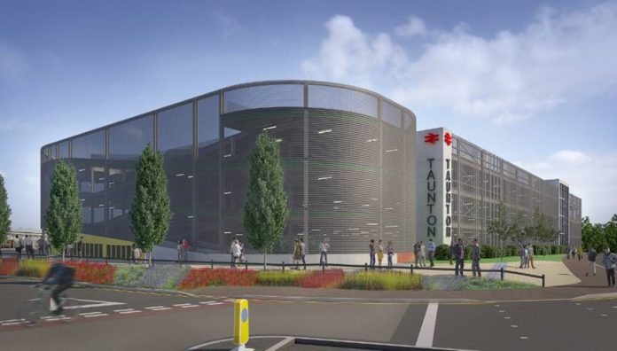
Design for redeveloped station at Taunton. (GWR)

Taunton station in Somerset is to be redeveloped over the next year, according to plans just released.

The station, which is operated by GWR, services trains from London to Penzance and also CrossCountry trains from Cornwall running up to northern England and Scotland.

GWR has now finalised contracts with construction company John Sisk & Son for the multi-million-pound regeneration scheme. To deliver the scheme, designed to help support the town’s economic development plans, the company is working with Somerset West and Taunton Council and the Heart of South West Local Enterprise Partnership, which is making a £4.6 million contribution from its Local Growth Fund.

Planned improvements will include a new multi-storey car park, additional cycle spaces, a new ticket office and entrance. An enhanced bus and taxi interchange will provide easier access to the town centre and the new £105 million Firepool waterfront community being developed by St Modwen just a short distance away.

Work is expected to begin this summer and be completed in spring 2020, improving the travelling experience for people visiting the town by train – a number that is expected to double over the next 10 years.

Somerset West and Taunton Council chief executive James Hassett commented on the announcement: “The redevelopment of Taunton railway station aligns with our ambitions for growth, and has long been a feature of our town centre regeneration plans. It is an integral part of our intention to link the station to the town centre with upgraded and enhanced pedestrian access along the River Tone through Firepool and the Coal Orchard.

“The provision of multi-storey car parking and public transport facilities is an essential part of the development in planning and investing for the future.”

UNIFE releases vision paper on Digital Trends in the Rail Sector

UNIFE, the Association of the European Rail Industry, has released a new vision paper on digitalisation that aims to bring the European rail supply industry’s views and objectives into the centre of the digital debate.

‘Digital Trends in the Rail Sector’ was prepared by the members of UNIFE’s Digitalisation Platform. It sets out the main priorities and ambitions of the European rail supply industry in relation to the digital technologies that are shaping the future of the rail sector in Europe and worldwide.

The vision outlined in the document focuses on five major areas – Big Data, Cybersecurity, Artificial Intelligence (AI), New Mobility Services and the Digitalisation of the Freight Logistics Chain – which UNIFE believes are making the greatest contributions to the digital transformation of the rail sector.

In the paper, UNIFE states that, while the rail sector is sometimes perceived as being conservative, the truth is that rail transport has always been a frontier of technological progress, with the supply industry leading the way. With digitalisation, the pace of change in the sector has moved up a gear. Roles have been transformed and new companies, as well

as business models, have emerged – such as Uber and Mobility-as-a-Service (MaaS). New concepts as well as new technologies create new possibilities, shortening the timeline of innovation and shaking-up the entire transport sector.

All of this has resulted in the deployment of digital and enabling technologies in rail being at an earlier stage when compared with other modes of transport. Therefore, UNIFE believes it is vital for the whole sector to maintain its commitment to making digitalisation, not merely an objective in itself, but rather a means to achieving more ambitious and overriding goals.


UNIFE’s vision paper Digital Trends in the Rail Sector is available to read online.

First TransPennine Express Nova 3 train handed over

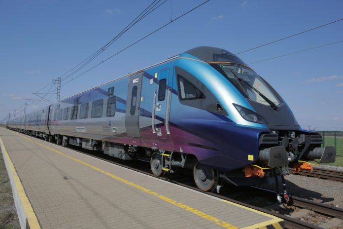
The first of TransPennine Express’s (TPE) new fleet of Nova 3 trains, which will initially come into service in the coming months between Liverpool Lime Street and Scarborough, has now completed testing and been accepted from manufacturer Construcciones y Auxiliar de Ferrocarriles (CAF) after it completed its fault free running.

This will allow TPE to begin training drivers and conductors ahead of the new train’s introduction into service later this year.

Each five-car train has 291 seats, compared to 181 on the current Class 185 trains operated on the route, as well as more luggage space, plug and USB charging points, free on-board Wi-Fi in both standard and first class and an entertainment system, Exstream, featuring the latest TV shows, news and films.

TPE has ordered 13 five-car sets of coaches, each comprising one first-class car, three standard class and a standard-class driving trailer. Trains will be hauled by Class 68 locomotives, leased from Direct Rail Services and maintained at Alstom’s Longsight depot in Manchester. Both the new sets of coaches and the Class 68 locomotives are owned by Beacon Rail.

TransPennine Express major projects director Chris Nutton said: “This is a key milestone in our new trains project, which will allow us to bring in these fantastic trains in the coming months.

“Although there have been a few bumps on the way, it’s brilliant that our plan is now coming together and our customers will be able to travel in comfort on modern trains with more seats later this year.”

TPE Nova 3 on test.

The Nova 3 fleet, which will be introduced onto the Manchester Airport to Middlesbrough service once it is established on the Liverpool to Scarborough route, is part of a larger, £500 million investment by TPE aimed at introducing a total of 220 new carriages and 13 million extra seats across the North and into Scotland by 2020.

The new fleet will also include 12 new five-car Class 397 ‘Nova 2’ electric multiple units, also from CAF, and 19 five-car Hitachi AT300 ‘Nova 1’ Class 802 bi-mode trains. Deliveries of both are expected this year so they can be introduced into service on long-distance routes from 2020.

New London Overground Class 710/2 train obtains conditional approval to run

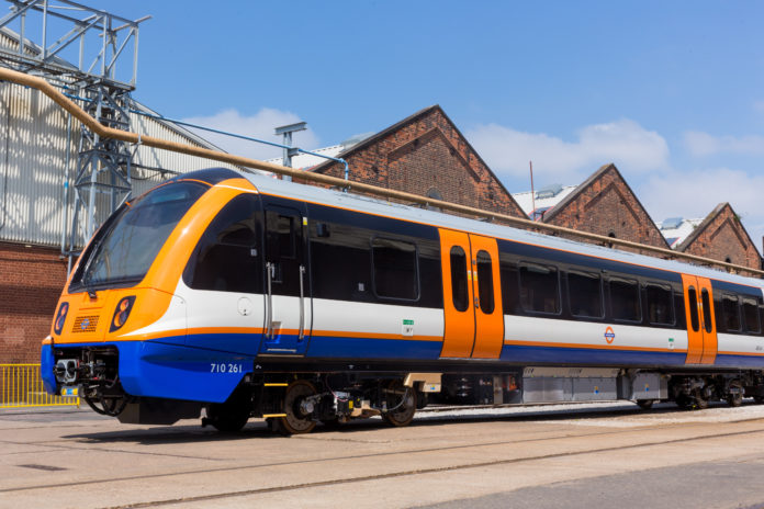
The new Class 710 London Overground trains being built and tested at Bombardier in Derby

Bombardier’s new Class 710/2 ‘Aventra’ train, destined for London Overground’s Gospel Oak to Barking and Watford lines, has received its first limited approval from railway regulator the Office of Rail and Road (ORR).

Originally planned to enter service in May 2018, the new trains have been dogged by ‘technical problems’ which have delayed the programme.

There are still outstanding issues.  The ORR approval limits the new train to “single unit operation only, fitted with AWS and TPWS (stand-alone mode only), GSM-R voice only, maximum speed of 75mph, 4-car dual voltage units 710256 to 710273 AC passenger operation only”.

In total, a list of 13 restrictions prohibit the use of Correct Side Door Enable (CSDE) and Automatic Selective Door Operation (ASDO) as well banning use of the de-icing system and setting speed restrictions.

There are also five conditions which have to be met. Interestingly, two of them require both Bombardier and operator Arriva “to reduce the risks of climbing and surfing in the inter-car area to a level which is as low as reasonably practicable (ALARP)”, so it seems the ORR is not only concerned with the safety of passengers but is now having to account for the actions of trespassers and joyriders as well.

Welcoming the industry to Railtex 2019

Railtex, the UK’s definitive exhibition of railway products and services, returns to Birmingham’s NEC next month. As always, the show will have an international flavour and is expecting visitors from more than 50 countries, with lots of exhibitors bringing products and services from countries in Europe, Asia and the US.

Natalia Charman, exhibition manager for Mack Brooks Exhibitions, told Rail Engineer: “Since its origins in 1993, what has made Railtex unique, and why the exhibition has stood the test of time, is that it encompasses the entire railway equipment, systems and services sector, and brings together these organisations in a collaborative and informative setting. It is the definitive exhibition for the industry and anyone with an interest in the sector should look to have a presence there.

“The industry continues to experience a period of growth, with passenger numbers expected to increase by a further 40 per cent by 2040. Alongside this, the transition to a digitally-led rail network and the key milestones of major projects, including HS2, Crossrail and the Great North Rail project, make 2019 a huge year of opportunity for the sector’s suppliers, buyers, infrastructure managers and operators.

“Beyond the main exhibition, we will once again be offering a comprehensive supporting programme, including insights from leading industry figures and a comprehensive seminar programme across the three days. Keynotes will be provided at Rail Engineer’s Seminar Theatre while the Railway Industry Association’s Knowledge Hub will host a selection of project updates and industry briefings from key figures.

“We look forward to welcoming the industry to Birmingham for three days of insight, learning and networking next month.”

Rail Delivery Group chief executive Paul Plummer added: “Record investment from the private sector will help to fuel the largest improvement in our railway since Victorian times. This will see customers benefit from the roll-out of 7,000 new carriages and improved stations across the country as part of the rail industry’s joint long-term plan.”

In other articles, Rail Engineer previews some of the exhibits that will be at Railtex as well as the Technical Seminar programme. For more information, including the latest list of exhibitors, please visit www.railtex.co.uk.