Home Blog Page 121

If it’s Tuesday it must be Olomouc

It is easy to sympathise with teachers who take groups of schoolchildren on educational visits, as they work hard to keep their charges together. Consider, then, the task of Felix Schmid and Bridget Eickhoff as they led a group of 40 railway engineers (and their luggage) from the Czech Republic to Switzerland via Austria. This took a week and involved 14 technical visits, four hotels, a sleeper train, travel on 24 other trains and 12 trams. The average start time was 07:45.

This was the IMechE Railway Division’s Annual Technical Tour, one which Felix and Bridget had spent months organising. For everyone on the tour, it was huge learning experience to see the manufacture, maintenance and operation of trains and trams, as well as learning from each other. The opportunity to have informal chats with senior engineers was particularly useful for the young engineers, some of whom contributed to this article.

In addition to the engineering experience, the group had to hone its time management, organisational and packing skills to keep up with the demanding schedule. The tour also provided an opportunity to visit cities that many of the group had never heard of.

Participants had made their own way to Prague where the tour started at 13:00 on Saturday 5 October with a short tram ride to a train maintenance depot.

České dráhy

In the Czech Republic, infrastructure maintenance is undertaken by the state infrastructure manager, SZDC whilst České dráhy (CD) is the state railway operator, although there are also some private operators. The Czech rail network is about two thirds the size of the UK’s railway and 31 per cent of it is electrified. Overhead electrification is a mix of 3kV DC in the north and 25kV AC in the south. There is a 20-year plan to convert the 3kV DC lines to 25kV AC.

Examining Elefants.

The visit was CD’s Prague maintenance centre, which is responsible for 90 EMUs, 247 DMUs, 75 diesel locomotives, 113 electric locomotives and 1,082 coaches. The EMUs include the Czech Pendolinos and the double decker “City Elefant” EMUs. CD has two other maintenance centres, at Pilsen in the west and Olomouc in the south.

At the Prague maintenance centre, which has 40 kilometres of track, the group visited its two maintenance sheds and saw loco-hauled coaches being maintained in one and Elefant EMUs in the other, where a wheel lathe had been installed a year ago. To make the best use of this lathe, CD is about to procure a wheelset preventative monitoring system.

Prague’s trams

Sunday offered sightseeing with a purpose. The funicular ride up the hill to Prague’s Petřin Tower viewpoint showed why this type of railway needs wheelsets with one double flanged wheel (to run on the continuous outside rail) and the other with no flanges (to cross breaks for cables in its fixed switches).

The funicular’s unusual wheelsets and fixed switches.

In the afternoon, the group visited the Prague public transport museum. This had many tram vehicles, illustrating the expansion of the city’s substantial tram system, which started in 1875 with the first horse drawn tram and had its first electric tram operating in 1891. Prague’s tram network now covers 141 kilometres with 35 lines.

The numerous trams, and other artefacts, in the museum showed how these vehicles had developed. They included a motor tramcar dating from 1901 and specialist vehicles such as a substation car, which had a transformer and rotary converter so that it could be connected to an AC substation to boost the overhead supply when required, such as during major sporting events.

The tour left the museum on the 1915-built tram 349 and its trailer car for a tour of the Prague tram system. Our driver, Helga, demonstrated the hard work and skill that is required to drive such historic trams.

Tram driver Helga.

Škoda

Monday started with a train ride to Pilsen to visit Škoda’s rolling stock plant on which Emma Armstrong, a graduate engineer from ScotRail, reports:

Continuing Škoda’s long tradition at Pilsen, Škoda Transportation has been manufacturing rolling stock here since the 1990s, particularly electric rail vehicles for suburban transport. The site runs an end-to-end process in the production of tram and locomotive vehicles, with EMU and carriages being manufactured at other sites throughout the Czech Republic. There is also a subsidiary company in Finland – Transtech Oy.

The factory consists of several sheds used in the building of coaches, refurbishment of vehicles and overhaul of bogies. The tour was limited to the assembly halls, paint shed and testing track. On display were vehicles at varying stages of assembly or overhaul including the Emil Zatopek locomotive (named after the famous Czech long-distance runner) and driving coaches from double-decker EMUs that are supplied to Deutsche Bahn and are capable of a top speed of 189km/h.

Interestingly, only electric traction vehicles are currently produced at this site. Although Škoda can produce diesel hybrid vehicles, customer demand remains focused on electric vehicles.

The current rolling stock manufacturing process begins with the welding of the initial body shell which is then transported through the plant for low-level equipment fitment, interior cabling and high-level fitment such as HVAC (heating/ventilation/air-conditioning) and pantograph assemblies. Škoda uses a 36-metre covered traverser to move vehicles during manufacturing.

Completed vehicles are initially tested using a short on-site test track. For more intense testing, the heavy rail rolling stock is sent to the Velim test track at Cerhenice, 150km away to the east.

Škoda manufactures almost all the required components, either at this site or other locations, to enable them to produce a fully Škoda product.

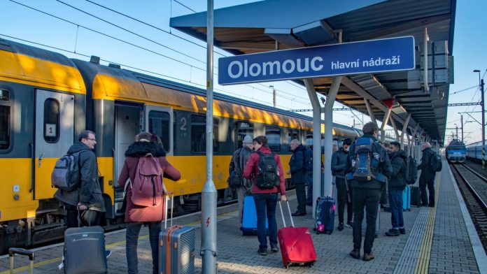
From Plzen, it was a 1¼-hour train ride back to Prague, then another 2½-hour train journey to Olomouc, in the southeastern part of the Czech Republic.

Olomouc’s tram train crossing.

Olomouc’s unusual crossing

Tuesday saw the tour in the city of Olomouc, where the group split into two. One party visited the OLTIS group headquarters to see its IT solutions for railway performance and operational management. The other group visited an unusual level crossing, as Nadeem Ahmed, a Network Rail graduate electrical engineer, reports:

In 2013, an extension to one of Olomouc’s tram lines crossed a single-track railway that catered for 28 trains per day. The resultant tram/train crossing was designed so that the tram wheel flanges run across the head of the heavy rail. As it does so, the tram wheel is not constrained. However, as the crossing is angled at 60 degrees, the other tram wheel is in the tram track.

The Olomouc council funded and built the level crossing over six months. The formation of the crossing began with a geo cell layer, with additional layers consisting of sand, concrete and steel meshes to provide enough strength to withstand the various loads. Trains go over this crossing at 80km/h, whilst trams cross it at 10 km/h.

Afterwards, the group visited the Olomouc’s public transport control centre to learn how timekeeping of trams and buses is monitored and controlled. Olomouc has a 31-kilometre tram network with 75 switches, two thirds of which have switch heaters as winter temperatures are typically -10°C. The city has 71 trams and 59 buses.

Brno’s trams

A 1½-hour train ride took the group to Brno, the Czech Republic’s second city with a population of about 400,000. Brno has a 70-kilometre tram network on which a fleet of 300 trams operate. It also has a 60-kilometre trolley bus network, with 140 trolley buses, and 46 bus routes. Ten trolley buses with batteries are being procured to allow for network disruption during road works.

Another chartered tram took the group to the main depot, with a stop to examine a newly installed 80km/h switch. For trams, this is a high-speed switch as the normal speed through street switches is 15km/h on the straight and 10km/h on the curve.

Examining high-speed tram switch in Brno.

At the depot, the systems used to monitor the timekeeping of each vehicle were explained, as were the ways in which passengers are kept informed. Five buses and four trams are kept on standby around the city, ready to be quickly brought into service in the event of any disruption.

The control room also closely monitors power consumption, with drivers receiving bonuses for low electricity use. Interestingly, control can temporarily switch off the heating on trolley buses and trams remotely if overall power consumption is too high.

During the depot tour, there was an opportunity to examine old and new tram bogies. Notable were the large braking solenoids on the trailer bogies, which are needed as the trams have no air system.

A second 1½-hour train journey took the group from Brno to Vienna.

Wiener Linien

Portal running gear, including traction motor of an ultra-low floor tram.

Vienna’s public transport system consists of a 29-line tram network of 181 kilometres, five U-Bahn lines totalling 65 kilometres and 43 daytime bus routes. It is operated by Wiener Linien, which has 526 trams, of which 168 have low floors. The tour visited the main workshops in Vienna, which undertakes tram heavy maintenance and component repairs, including bogies, traction motors, wheelsets and brake gear.

Of particular interest was the opportunity to inspect the unusual suspension and drive system of the ultra-low-floor trams supplied by Siemens between 2006 and 2015. These consist of a series of vehicle modules with portal running gear in between. There is a rigid connection between the driving cab module and the adjacent module, between which is the portal gear with single trailing wheels. Other modules are supported at one end by the portal gear through the secondary suspension and flexibly coupled to the next one. These portals have 52kW asynchronous traction motors driving each single wheel.

These trams are 36 metres long, which presents a problem as the workshop traverser, constrained by the workshop’s columns, is only 30 metres long. For this reason, the traverser is about as wide as it is long to accommodate trams on its curved track.

Traktionssysteme Austria

The group’s next call in Vienna was to the manufacturing plant of Traktionssysteme Austria (TSA) as Franziska Schmuecker, a project engineer for Eversholt Rail, reports:

TSA is an independent manufacturer of traction motors and gearboxes for rolling stock and road vehicles. The company’s values – “Innovative. Independent. Impassioned.” – were clear from the start of the visit, which was split in two parts: a series of presentations on the history of the company and its products (including UK products such as those for the new Glasgow Subway trains) followed by a tour of the production facilities.

The first technical presentation outlined the different traction motor cooling concepts used by TSA, which included self-ventilation, forced ventilation, liquid cooling and air cooling. Motors can be either an enclosed design or an open design using fresh air to cool the motor. Another presentation explained the advantages and disadvantages of different motor suspension arrangements.

One presentation explained the latest permanent-magnet traction motors, which provide a superior power output (up to 67 per cent increase) and torque (48 per cent increase) for the same motor size. Where size and weight are constraining factors, this is a great advantage.

As with all innovations, there are challenges to overcome, mainly controlling the induced voltage at higher speeds, which leads to the need for a separate traction inverter to control each motor. From all the presentations, it was clear that TSA is highly flexible in the projects and types of motor it delivers.

The presentations were followed by a tour through the production facilities, following the manufacturing process from the stamping of the rotor and stator laminations to the finished motor. Almost everything, except for the production of the standard coils, is done in-house, including the testing of the finished motor. TSA produces around 6,000 motors per year in this facility.

Producing yellow plant

Thursday started with a 200-kilometre train ride, at up to 250km/h, on the upgraded Austrian West Railway to Linz. Here, the tour visited a well-known manufacturer of yellow plant as Calum McLean, an assistant electrical project engineer with Network Rail describes:

Plasser and Theurer manufactures a major proportion of the world’s track maintenance machines. The range includes tampers, for which the company is perhaps best known, as well as machines for ballast management, stabilisation and control, ballast bed cleaning, formation rehabilitation, material logistics, the renewal and laying of tracks and turnouts, mobile rail treatment and the measurement, installation and maintenance of overhead lines.

If a customer’s requirements are not fulfilled by the standard range, special purpose machines can be manufactured as well. In any case, all machines are custom built to individual customer requirements and training is provided at the Linz plant for each machine.

It is not necessary to be a track engineer to appreciate how these machines have revolutionised track renewals and maintenance. For example, Plasser and Theurer advises that its machines can renew 2.6km of track per hour, compared with a 100 metres of track per hour when such machines were not available.

It was impressive to see the work that goes into manufacturing these machines, particularly as the company manufactures nearly all its own parts to ensure product quality. Every year, the Linz site produces around 150 machines of varying types with a workforce of 1,800. Despite this apparent complexity, bogie production has been standardised – there are only two basic types of bogies for all types of machine, albeit with varying track gauges.

Linzer Linien

Unlike other trams seen on the tour, those in Linz are 900 mm gauge. The city has a five-line, 61-kilometre tram network with 62 trams. 56 of these are low-flow single ended trams built by Bombardier, including Cityrunner trams, supplied from 2002, and Flexity Outlook 2, delivered from 2011. There are also four double ended Flexity Outlook trams with modifications for steep gradients as well as three 1974 trams that were rebuilt in 2010 with new running gear which are also suitable for steep gradients.

After a depot tour, the group boarded one of the rebuilt 1974 trams for a ride to the Pöstlingbergbahn museum, which explains the history of one of the world’s steepest adhesion railways. This opened in 1898 and climbs 255 metres in 2.9 kilometres, with a maximum gradient of 11.8 per cent (1 in 8.5). After seeing the museum, the tram took the group to the top of the Pöstlingberg, a hill overlooking the Danube valley.

From Linz, the group travelled overnight to Switzerland on cramped double-decker sleepers.

Stadler

After the sleeper arrived at Buch early on Friday, a local train and bus took the group to the site of a former seaplane factory on Lake Constance that is now Stadler’s manufacturing plant. Abigail Carson, a consultant engineer for Ricardo Rail, reports on the tour’s visit to this facility which, for her, was the highlight of the tour:

What impresses about Stadler is its lean production and how it achieves mass production combined with tailor-made solutions. The variety of rolling stock Stadler produces is impressive, from locomotives bound for California, Merseyrail’s new trains, double-decker KISS trains and compact Glasgow Subway trains – all with completely different body structures and sizes with vastly different design requirements.

Walking through the facility, it was interesting to see how the mass-produced, bare aluminium sections were transformed into such widely differing trains. It was clear that Stadler is growing and expanding with ease, supplying rolling stock globally.

The production layout is simple, logical, and easily adaptable. Each step of the manufacturing process is lean and efficiently timed. There is a coherent system, with a well-disciplined workforce and robust processes. The entire facility is spotless and has an almost clinical feel.

It was interesting to learn how Stadler utilises its expensive machinery by overlapping shifts. However, there are noise challenges associated with the surrounding villages, so sequencing the processes for the time of day is vital.

Appenzeller Bahnen

The remainder of the tour was spent in the rolling hills of eastern Switzerland, where train services are provided by Appenzeller Bahnen. Friday afternoon was spent experiencing the company’s two rack railways. The first, from Rheineck, by Lake Constance, was the 1.9-kilometre rack railway to Walzenhausen, which climbs 272 metres at a maximum gradient of 25 per cent.

From here, the group, and its luggage, just fitted onto a PostBus for a 20-minute ride to Heiden, which is 794 metres above sea level and the upper terminus of the 7.2-kilometre rack railway that descends 396 metres to Rorschach at a maximum gradient of nine per cent. The rack railway depot at Heiden, which was commissioning double-deck buses made in Scotland for the Swiss PostBus system, provided an insight into rack railway traction and braking systems. An examination of one of the motor bogies showed its braking system and the complex drive that enables the trains to be driven by either their rack or rail wheels.

Rack railway switch outside Heiden depot.

The future of both these rack railways is currently being assessed, as they only cover about 30 per cent of their operating costs. Options under consideration include closure, automatic operation or, for the Heiden railway, which only has an hourly service, investment in extra capacity to generate extra revenue.

Whilst there is some doubt about the future of the Appenzeller Bahnen’s two rack railways, Saturday’s tour revealed the significant recent investment in its one-metre gauge adhesion railways. At St Gallen, the party’s train went through a 705-metre tunnel, opened in October last year, to replace a steeply graded part of the route that was a rack railway. This enabled a 15-minute service frequency to be introduced.

From St Gallen to the depot at Gais, the group travelled on a Stadler-built ‘Tango’ low-floor light-rail vehicle, which was one of eleven such trains delivered last year at a total cost of £66 million. These 53-metre-long units consist of two sets of three modules. The centre module of each set is mounted on a bogie and supports the adjacent modules, which each have only one bogie. This gives the six-module unit six bogies in a configuration that is designed for the sharp 30-metre radius curves on the route, which has a maximum gradient of eight per cent.

At Gais, there was an opportunity for a detailed examination of these units, together with the larger, 59-metre-long ‘Walzer’ low-floor EMU, five of which were also delivered last year at a cost of £31 million. The group travelled on one of these units from Appenzell to Gossau, to change onto the Swiss equivalent of a Pendolino (RABDe 500 jointly developed by Bombardier and Alstom) to Zurich and the end of the tour.

Shared learning

After seven intense days, it was clear that everyone had learned much from the visits and from each other. The 14 visits were a rare opportunity to study heavy and light rail maintenance and production outside the UK. The young engineers on the tour commented that they particularly appreciated the opportunity to see rail vehicle manufacturing at Škoda, Stadler and Plasser & Theurer, as well as the traction motor production at Traktionssysteme Austria.

Close scrutiny of the tram systems in Prague, Olomouc, Brno, Vienna and Linz showed the differences between main line and light rail practice. Many commented on the portal suspension of Vienna’s ultra low floor trams, Olomouc’s tram train crossing and the wide variety of tram bogies seen. The tour also highlighted the lack of light rail systems in the UK. Brno, for example, has a 70-kilometre tram network and is the same size as tram-free Leicester.

The way that Apenzellerland railways overcome the challenges of the Swiss terrain was also impressive and thought provoking. Indeed, one senior group of engineers debated the workings of rack and pinion traction well into the night. Although it was unclear whether the new Tango units were trains or trams, they are perfectly adapted to their sharply curved, one-metre gauge track with impressive acceleration up an eight per cent grade.

As one younger member of the tour put it, “we can learn so much from how things are done in different countries”. Providing such an opportunity was just one reason why the Railway Division’s Annual Technical Tour is such a worthwhile event.


Participants in the IMechE Technical Tour would like to thank Felix Schmid and Bridget Eickhoff, who organised and led the tour, all the group’s hosts in the Czech Republic, Austria and Switzerland, the event’s sponsors: Angel Trains, Beeston Rail Standards, Birmingham University Alumni, Eversholt Rail, Malcolm Dobell Consulting Ltd, Manchester Engineering Consultancy and Unipart Rail.             Thanks also to Emma Armstrong, Nadeem Ahmed, Franziska Schmuecker, Calum McLean and Abigail Carson for their contributions to this feature.

A little sand in the right place works wonders

Part 3, Operational Trials

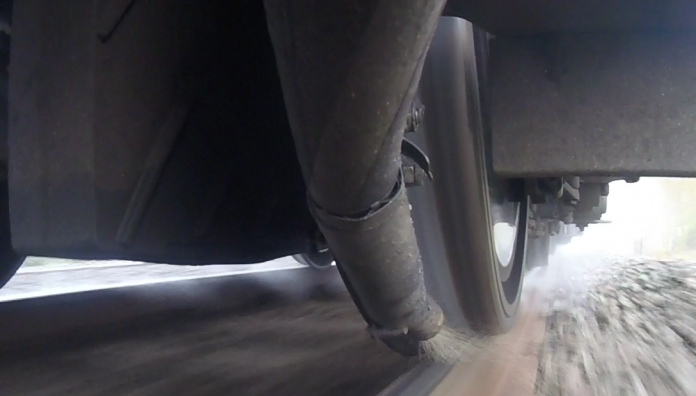
In November 2017 (issue 157), Rail Engineer reported on trials undertaken at the Rail Innovation and Development Centre, Melton of multiple variable rate sanders fitted to a GWR class 387 EMU, with the expectation that service brake performance would be significantly improved in poor adhesion conditions.

Then, in May 2018 (issue 163), Rail Engineer reported on a seminar held by RSSB to present the results of those tests. They reported that 6% G deceleration could be achieved, even in very poor adhesion conditions. At the end of that seminar, RSSB appealed to members to volunteer to help them take the project forward.

Rolling forward to October 2019, at the invitation of RSSB’s Aaron Barrett and Paul Gray, Rail Engineer arrived at Redditch station – one end of the Birmingham Cross-City line – to witness further tests that were carried out over several Sundays in October 2019 and to learn what had happened since 2017/8.

West Midlands Trains, the operator trading though the West Midlands Railway and London NorthWestern Railway brands, had volunteered to work with RSSB as they were particularly keen to improve the reliability of the Cross-City line, where, as operations director Mark Steward explained, there are significant leaf fall problems from trees on third-party property. WMT routinely implements an autumn timetable, which slows the trains and harms punctuality.

Since Autumn 2018, enhanced adhesion performance data has been collated and analysed on the Cross-City Line, including additional train traction/braking monitoring equipment on Class 323 units. Although this has provided further insight into the effectiveness of the various low-adhesion treatments, only limited results were obtained as the drivers drove mostly in step 1, the lowest brake rate, and provoked little WSP (wheel-slide protection) activity.

Undaunted, two units have been equipped with variable rate sanders, a) to replace the fixed rate sanders dispensing on the third axle in the direction of travel and b) additionally to apply sand under the seventh axle of these three-car units. A further change since the original tests is that sander operation is now automatic in response to the train WSP equipment.

The Class 323 train that was used for the trials.

Test set up

The purpose of the test was two-fold. Firstly, to ensure that the performance of the improved sanders on the Class 323 was at least as good as that on the previous trial, and secondly, but most importantly, to enable WMT drivers and health and safety representatives to experience how the system works and to be able to use higher brake rates, steps 2 and 3, with confidence.

Arrangements were quite similar to those for the 2017 tests, except for the site and the rolling stock. Despite a very strong desire not to disrupt passenger services, all concerned saw the benefit of demonstrating the system to drivers who would operate the trains on infrastructure that they drive every day – hence the Redditch site.

The paper tape that was laid on the track to replicate fallen leaves.

In summary, paper tape was applied onto the running rails over a length of approximately 750 metres. The tape was wetted with train-mounted water sprays to provide the low adhesion conditions, and the train was then run over the tape for two out-and-back moves to bed the tape in.

Then several runs were carried out, braking from 55mph without sanding to condition the rails before a step 1 brake was used to demonstrate slide at a low brake rate and thus poor adhesion. Finally braking runs with sand in steps 2 and 3 were demonstrated.

One of the safety control measures was to lower the pantograph before entering the paper tape zone and not raise it again until the train had coasted off the tape. This measure ensured that there were no adverse effects from possible poor traction return paths whilst on the paper tape; a lesson learned from the 2017 tests.

Another precaution was the provision of a temporary additional compressed air tank. This provided a reserve of compressed air whilst the pantograph was down and the compressor out of action.

To illustrate the effect of the enhanced sanding, a step 3 brake with no sand only managed to reduce speed from 55 miles/hour to 40 miles/hour by the end of the paper tape (a speed reduction of 15 miles/hour over the 750 metres travelled).

Once the enhanced sanders were activated for a repeat test, the brake application was so successful that the brakes had to be released early because there was barely enough momentum left to coast to the end of the paper tape so that the pantograph could be raised again. Your author was in conversation with Parvaiz Elahi, the ASLEF health and safety representative, during the step 3 test with sand and we were both suitably impressed.

ASLEF representative Parvaiz Elahi (left) discusses the trials with DB ESG’s Andrew Lightoller.

A further innovation was the method of controlling the possession. Network Rail’s operational sponsor and organiser of the tests, Dominic Mottram, said this is a comparatively unusual Signal Protection Zone, where both incursion into and out of the possession is controlled solely by signals held at danger. Whilst SPZs are not a new concept to the railway, the success and positive reaction to their implementation for this project has already attracted attention from other parts of Network Rail.

Dominic added that this project was a team approach with Network Rail, RSSB, West Midlands Trains, DB ESG, Ricardo Rail playing leading roles and with a very important stakeholder in the form of the West Midlands Rail Executive.

Results

What follows are the impressions from the day; RSSB will publish formal results in due course.

Mark Steward of West Midlands Trains told Rail Engineer that the test objective – building driver confidence when driving relatively normally on contaminated track – had been delivered. He said that the next step is to introduce the two units into passenger service. Mark was aiming to use experienced drivers on these modified units, and to compare their performance with the performance of the trains in front and behind using ‘big data’ analysis techniques to assess performance in service.

He added that, as this is an experiment, he recognises that there will be a risk of station over-runs when driving this way, and will manage that risk appropriately, both for safety of the railway and for driver competence management, such that drivers will not be penalised if they are driving modified units on contaminated track using the techniques tested.

He added that he had not been prepared to authorise the trial unless he was confident it was safe and his visit was partly to gain that confidence.

Drivers, their representatives, and their managers were most impressed with the system. If this autumn’s service trial is successful, it is to be hoped that the system will be fitted to many more trains over the next few years.

Thanks to Paul Gray (RSSB), Mark Steward (West Midlands Trains), Dominic Mottram (Network Rail), Andrew Lightoller (DB ESG) and Liam Purcell (Ricardo Rail) for their assistance with this article.

Locos go bi- and tri-mode!

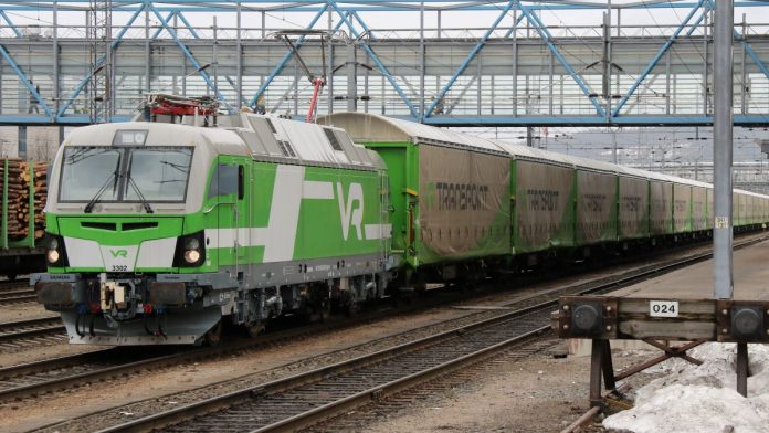
Siemens Vectron for Finland – 3302 seen at Jyväskylä operating as an electric on 25 April 2018. (Keith Fender)


Guest writer: Keith Fender

Rail Engineer has previously looked at several innovative forms of traction for new passenger trains; from the Hitachi built bi-mode (electric / diesel) trains now widely in use in the UK (with other bi-modes such as the Class 769 conversions coming into service soon) to the iLint hydrogen powered train in passenger service in Germany (with several hydrogen powered projects announced in the UK too now).

However, until now, we haven’t looked in detail at the developing range of bi or tri mode locos now being designed and built for use in the UK and Europe.

Not a new idea

Dual mode, bi-mode, or electro-diesel locos are not new in conceptual terms. Diesel locos equipped with third rail pickup were developed for use by the New Haven Railroad in the mid-1950s in New York City, where steam and diesel usage was prohibited from 1903, leading to early electrification and time-consuming traction changes from steam to electric outside the city limits.

Siemens supplied electric mining locos equipped with auxiliary petrol engines to a diamond mine in South Africa as long ago as 1925!

British Rail and English Electric built a fleet of 49 Class 73 third-rail electric locos equipped with 600HP diesel engines from 1962 onwards and converted another ten older Class 71s to Class 74 (all since scrapped). 52 years later, some of the Class 73/1 versions are still in service, with the original engine, with freight company GB Railfreight, although others have been completely rebuilt as Class 73/9 with modern engines and traction equipment.

Last Mile vs. Main Line diesel

All of the major European manufacturers have developed bi-mode or hybrid locos in the last decade, but they vary considerably in terms of power rating – and orders received.

The initial trend of all the manufacturers was rather like the old BR Class 73/74 – to provide ‘Last Mile’ diesel power, enabling an electric loco to access non-electrified branch lines and yards. The diesel power installed was usually a small engine (around 180kW or 240HP, so around the power of half the old BR Class 73) hidden in an equipment cupboard inside the loco.

Bombardier and Siemens between them have sold the most ‘Last Mile’ equipped locos with Siemens selling 112 Vectrons fitted with 180kW diesel power modules and Bombardier 120 Traxx AC locos (90 of which were in use at mid-2019); the latest with 230kW diesel power modules and 40kW battery packs (used to provide a short term traction boost when the loco is operating in last mile mode).

Within these totals, Siemens is currently supplying 80 1,524mm gauge Vectrons (see top of page), each with two 180kW last mile diesel power packs, to Finnish state railway operator VR to enable replacement of diesel trip/shunting locos on non-electrified freight routes.

Bombardier has supplied ‘last mile’ diesel modules as an option since it launched the Traxx 3 variant of its long running Traxx design; the latest version, the Traxx 3 Multi System that is now undergoing final Europe-wide approval testing, can combine a quadri-voltage (1.5/3kV DC and 15/25kV AC) electric loco with a 230kW diesel power pack /40kW battery pack for last mile operation.

Austrian freight operator Wiener Lokal Bahn has six Class 187 ‘Last Mile’ equipped Traxx 3 locos on order. The locos are also equipped with remote control so can be driven in yards etc by staff on the ground. In the picture taken at Bombardier’s Kassel factory on 4 April, the loco is running on diesel and the driver is on the ground next to the loco. Side lights beside the driver’s doors illuminate when the loco is being driven remotely (they are different colours for diesel and electric operation).

WLC (Wiener Lokalbahnen Cargo) 187 324 diesel outside Bombardier’s Kassel factory, 4 April 2019. (Keith Fender)

New Trend – bi-mode main line locos

Before it sold its transportation, business based near Valencia in Spain to Stadler in 2016, Vossloh had identified the market opportunity for ‘go anywhere’ locos that could operate under catenary but which also have enough diesel power to operate through passenger and freight trains away from the electrified network.

Instead of just including a ‘last mile’ diesel module within a modern electric loco, the EuroDual loco range, which Stadler is now offering, is a capable electric locomotive that also has a powerful 2,800kW diesel engine.

Class 88 away from the wires – a guest appearance on the Severn Valley Railway in May 2018. (Keith Fender)

Vossloh also sold two versions of its initial UK-Dual design, based on the UK Class 68 (UK Light diesel loco) bodyshell, although deliveries were made by Stadler after they took over the business. Ten ‘UK-Dual’ – 4,000kW 25kV AC electric and 700kW diesel (using a Euro IIIB emissions compliant Caterpillar C27 diesel engine) – Class 88 locos were ordered by Beacon Rail in September 2013 for DRS using essentially the same body shell as the Class 68. Like the Class 68, the Class 88 used ABB traction equipment.

The Class 88 order was followed in October 2013 with an order for 50 similar but 1,067mm gauge locos for passenger services in South Africa, for delivery in 2015-16. A modified version of the ‘UK Dual’ bodyshell was chosen to accommodate the South African loading gauge. Whilst some of these were built, in advance of the UK Class 88s, deliveries have been suspended due to ongoing contractual problems in South Africa.

Late in 2018 came news of a planned new variant of the UK Dual Class 88 – but this time a tri-mode loco – with diesel, overhead electric and also battery power.  Beacon was once again to be the buyer, but the end customer would be UK stock-movement specialist Rail Operations Group. So far, the locos have not actually been ordered, so technical details are limited, but lithium-titanate batteries would be fitted to store energy from regenerative braking plus the overhead supply.

The design concept assumes use of the batteries to increase starting power, enabling heavier trains to be moved and to supplement diesel power for short periods, for example when going up gradients. The Class 93 may feature a slightly more powerful diesel engine than that used in the Class 88.

Pan European bi-modes

Some of the big European manufacturers are aiming to supply freight operators with locos that are powerful enough, as diesels, to handle freight on non-electrified secondary routes but also are powerful electric locos for use on electrified trunk routes. This is especially true in countries such as Germany or Austria, where most diesel-hauled freight currently operates for hundreds of kilometres under electric catenary (as much as 80 per cent of the time in Germany).

Very few ‘pure’ main line diesel locos have been built for use in Europe in the last decade; Stadler’s Euro 4000 six-axle design has taken the majority of orders, with Siemens and Alstom selling very few. Bombardier has sold 51 of its Traxx Multi-Engine (Traxx ME) loco to operators in Germany – this design has four small diesel engines instead of one large one, offering cheaper maintenance, the ability to operate with one or two engines switched off when running light, and redundancy.

Spanish manufacturer CAF built the first big European bi-mode locos over a decade ago. Nine six-axle ‘Bitrac’ electro-diesels were built for use in Spain, but CAF sold no more. These 4,500kW electric / 3,600kW diesel locos (fitted with two MTU 12V R43L engines) are now owned by Beacon Rail and leased to French Railways’ international freight subsidiary Captrain.

EuroDual for ELP under construction at Stadler’s Valencia factory in early 2019. (Keith Fender)

The Stadler EuroDual design, as already mentioned, is a powerful six-axle electro-diesel which utilises the same 2,800kW Caterpillar C175-16 diesel engine (as used UK Class 68 but the EuroDual uses the more-modern Stage IIIB version) in addition to offering 6,150kW (power at wheel rim) as a 25kV AC electric.

Stadler has sold 30 EuroDual locos, and agreed options for 70 more, to new Swiss-based leasing company European Loc Pool (ELP). Some are currently being tested whilst others are in production at Stadler’s Valencia factory. For the first batch of ten locos, ELP ordered two locos specifically for use in Scandinavia with winterisation (for temperatures as low as -40°C) and signalling systems for use in Norway and Sweden, plus eight locos for use in Germany. All ten locos are equipped for operation from 15kV/25kV AC catenary.

The 126 tonne locos have a starting tractive effort of 500kN (under both diesel and electric power) and a top speed of 120km/h (although they could be geared for 160km/h if required). The three-axle bogies are an improved form of those used under the Stadler Euro 4000 CoCo diesel design and each bogie has three asynchronous traction motors. Initially, the ‘German’ locos are only designed for use in Germany, although Stadler intends to secure approval for operation in other countries in the future.

Further orders

In addition to the ELP order, Stadler has orders for ten EuroDual (15kV/25kV AC bi-mode) locomotives for German operator HVLE. ITL (owned by SNCF French Railways via Captrain) also ordered four locos in the same configuration for use in Germany in late 2018. The prototype EuroDual, which is a 25kV AC/1.5kV DC bi-mode version, has been sold to VFLI in France – unlike the other locos this loco is equipped with French safety systems.

During 2019, Stadler has announced an order for seven locos for Turkish open access operator Körfez Ulaştırma, due for delivery in 2021. Körfez Ulaştırma will use the locos to operate 2,000-tonne oil trains in Turkey. Stadler will also maintain the fleet.

Stadler says it has now sold 74 of its new EuroDual six axle locos. Stadler has also announced orders for 22 bi-mode locos for Spanish national rail infrastructure manager ADIF for delivery in 2021/22 – technical details for this order have not been announced.

Siemens presented the first of its new ‘Dual Mode’ (DM) version of the Vectron locomotive in March 2019. Designed as a mid-power diesel loco (2,400kW) and mid-power AC electric loco (2,000kW) in one four-axle loco, the Vectron DM offers the maximum flexibility to freight operators for traffic that originates or is destined for places on non-electrified lines but which uses the electrified main line network for the trunk-haul part of their routes.

Siemens estimates that German freight operators, currently using over 700 older diesel locos, could save 53 per cent of their energy and maintenance costs, plus reduce CO2 emissions by 950 tonnes annually per locomotive, by using the new Vectron DM instead of an existing diesel loco.

Siemens developed and built the first German Class 248 Vectron Dual Mode loco from scratch in six months. This fast concept to prototype period was possible as the Vectron Dual Mode uses bogies and traction motors from the existing diesel-only Vectron DE platform and these were already available as, so far, only nine Vectron DE Class 247 locos have been built since the model’s launch in 2010.

The Vectron Dual Mode will now probably replace the Vectron DE in Siemens’ range, although the company would potentially continue to offer it to customers outside Germany if the order quantity was economically attractive.

The 90-tonne loco is capable of 160kmh. It is equipped with a 2,500-litre diesel fuel tank and the German PZB signalling system (although it is pre-equipped for ETCS). Whilst not designed for passenger operation, Siemens says it could be equipped with electric train supply for air conditioning etc if that was requested. Siemens is currently testing the two prototypes and seeking orders for the new Vectron Dual Mode with delivery from Q4 2020 promised.

The MTU 4000 engine used in the Vectron Dual Mode, fitted with a set of large air filters, meets EU Stage V emissions standards (as does the four-engined, pure-diesel Bombardier Traxx ME).

NJT ALP 45DP leaving Seacaucus Junction, New Jersey, June 2017. (Keith Fender)

Across the Atlantic

Bombardier has also built bi-mode locomotives, but not for use in Europe. Its ALP 45DP BoBo electro-diesel has been supplied to commuter rail operators in New Jersey (USA) and Montreal in Canada. New Jersey Transit (NJT) has a fleet of 35 and is currently adding a further 17.

The 4,000kW (electric), 2,700kW (diesel) ALP45DP has an axle loading of 34.1 tonnes (compared to 22.5 for the four axle European Siemens Dual Mode). The North American loco is fitted with two Caterpillar 3512C HD engines and, in the case of the NJT locos, works from two traction voltages too (12.5kV 25Hz AC and 25kV 60Hz AC) at up to 125mph (electric only).

Siemens has also built bi-mode locos for US commuter operator Long Island Railroad in the 1990s (23 DM30AC electro-diesels delivered from 1996).

Adding a third dimension – battery power

While developments in battery technology are leading to all major manufacturers looking at battery power for passenger trains, it is increasingly being considered for locomotives too.

Battery powered locos are not new – the first named “Galvani” was demonstrated by its inventor Robert Davidson between Edinburgh and Glasgow in 1842!

During the 19th century, many manufacturers built small battery shunting locos but, using lead acid batteries, they were heavy, slow and had limited range.

A British battery loco that is 102 years young this year, and still in daily use, seen at Hythe in August 2019. (Keith Fender)

The Hythe Pier railway in Hampshire uses two small Brush-built electric locos delivered as battery locos in 1917 to work in an armaments factory. They are still in use, although converted to third rail operation, as this August 2019 picture shows!

Battery technology has moved a long way in the last few years. Batteries are now being used daily for trams in many cities – although often only for short sections – and they are now seen by all the major manufacturers as a key traction option for the future. As mentioned earlier, the Beacon/ROG Class 93 design would use batteries, primarily to enhance starting performance but also to store energy.

Combining modern battery technology with electric traction systems and, in some cases diesel engines, as well, could be the next trend in locomotive design. Some such locos already exist – Chinese rail engineering firm CRRC has delivered electric locos with battery packs, charged via regenerative braking or ground supply, for use operating engineering trains on metros in Sydney (Australia), Hong Kong and Guangzhou (China). Maximum Speed using battery power is 40km/h.

CRRC loco for DB at Innotrans 2018. (Keith Fender)

CRRC has also supplied two diesel-battery hybrid shunting locos to German Rail operator DB for use operating maintenance trains on the Hamburg S-Bahn network (one was displayed at Innotrans in 2018). A total of four locomotives are on order, to be equipped with lithium-titanate batteries capable of generating 150kW of traction power (or, with the 250kW diesel engine, a combined 400kW).

In August, Welsh rack-railway operator the Snowdon Mountain Railway announced it has ordered two battery-diesel hybrid locomotives from British manufacturer Clayton Equipment. The new locos will replace older diesels and will use regenerative braking on the descent to generate energy for use on the next ascent to the summit of Snowdon.

Several smaller European manufacturers, including Gmeinder, are now offering battery hybrid options for previously diesel-only designs; the Gmeinder DE75 BB four-axle shunter has a 354kW Caterpillar engine and a lithium-ion traction battery pack producing 600kW of traction power between them.

Russian manufacturer Transhmash unveiled a diesel battery hybrid loco in 2019, equipped with a 200kW diesel engine plus a 240kW lithium ion battery pack.

Vossloh Locomotives, which is being bought by Chinese firm CRRC, offers its DE18 four-axle diesel with 150kWh battery packs in addition to the standard ‘straight’ 1,800kW diesel version.

Turkish manufacturer Tülomsas has rebuilt mid-1980s vintage Turkish State Railways DE11000 diesel locos with smaller 300kW diesel engines plus 400kW of lithium-ion battery power. The resultant hybrids are able to run on either or both power sources as required.

DB Regio H3 operating in battery mode at Nuremberg Hbf on 13 December 2016. (Keith Fender)

Alstom has been building diesel-battery hybrid locos designed for trip freights, shunting industrial plants and empty stock moves in Germany for five years. The ‘H3’ three axle design equipped with Nickel-Cadmium batteries has sold fairly well and is in use in Germany and central Europe. A bigger four axle development of the technology – the ‘H4’ – has been developed, but the only order so far for Swiss Railways (SBB), who have ordered 47 Class Aem 940 locos for infrastructure trains. These are classic electro-diesels equipped with two Caterpillar C18 diesel engines.

In 2017, CAF announced it had won a contract to supply twelve 1,000kW electric/battery hybrid locos to Paris metro and rail operator RATP to operate engineering trains on the RER network. The locos will be produced at CAF’s French plant and incorporate ten tonnes of nickel-cadmium batteries, as well as traditional pantographs for overhead power collection.

Battery power for passenger trains

Hitachi has announced plans to develop battery-powered trains for the UK market and has already delivered them in Japan. The wider Hitachi group is already a major automotive battery supplier and Hitachi Rail Europe has previously said it expects the rail market to piggyback the developments in battery technology for road transport; the market for which, on a global scale, is many times bigger than the market for rail.

The company has been developing hybrid and battery technology since 2003, largely in Japan. In 2007, it fitted a Class 43 HST power car with battery technology and ran trials in the UK in partnership with Network Rail. The train, named Hayabusa, completed over 100,000 km. The result was a 15 per cent fuel saving and a silent and emission-free movement out of stations.

In 2017, Hitachi delivered the BEC819 series ‘DENCHA’ (Dual Energy Charge Train) BEMU to Japanese operator JR Kyushu. Now in passenger service, it is operating for 50km route on battery power, between recharges.

Hitachi is now planning to add batteries to its UK bi-mode trains, which will be used alongside diesel engines to form a tri-mode hybrid power system. Hitachi expects not only to boost acceleration rates, but to cut fuel consumption (and costs) by 10 per cent or more. Hitachi also point out that batteries can benefit station environments too. Using them for initial operation in and out of busy stations can cut noise and air pollution, which is highly significant as air quality at some UK stations breaches safe legal limits significantly due to diesel emissions.

Siemens battery train on test in Austria.

Siemens, using lithium-titanate battery units, and Bombardier (lithium-ion batteries) are already testing battery equipped EMUs in Germany and Austria respectively.

Alstom’s new iLint hydrogen-powered train, which is now in service in Germany, is a hydrogen/battery hybrid with a sophisticated control system that uses batteries to store energy from regenerative braking and minimise fuel-cell load variations. As hydrogen fuel has a greater energy density than batteries, it clearly has some passenger multiple-unit applications and has also been used for shunting locos in America and China. However, it currently seems unlikely that hydrogen will have any major role in locomotive design.

Stadler has developed and sold battery-equipped versions of its Flirt EMU – 55 battery/15kV AC overhead power trains for use by NAH.SH (the public transport system in Schleswig-Holstein) in northern Germany and 24 tri-mode 25kV AC/ diesel and battery versions for use in the Welsh valleys by Transport for Wales.

Batteries with everything?

The convergence of differing propulsion systems, with both electric traction equipment and even diesel engines becoming more compact and needing less space in a locomotive car body, plus the likely future development of battery technology, could lead to the disappearance of ‘simple’ diesel or electric locos. If batteries are cheap and powerful enough, they can power movements in depots or assist with self-rescue for failures and could become standard.

One major European freight operator calculated that simply restarting an older, 1960s vintage diesel loco and moving it from one end of a yard to the other costs around £50 a time! With batteries, such costs disappear.

Battery technology for transport use is developing rapidly, and billions are being spent by the automotive industry to enable this. The UK Automotive Council estimate that the energy density of batteries could quadruple by 2035, yet even this is only one tenth of the energy density of diesel.

Hence, for more demanding rail applications such as heavy freight, high speed trains or even high-frequency metro-style services, it is unlikely that batteries will ever have a major role – although anyone re-reading this in 2050 might know better!

The quest for a cleaner railway

The UK’s railway is eliminating carbon. You must have noticed. The government has pledged to get all diesels off the railway by 2040 and have it “Zero Carbon” by 2050. Scotland, trying to get one over on England as usual, plans to decarbonise its railways by 2035.

But what does that mean? The obvious answer is electric traction, and that means electrifying the railways.

Scotland does indeed have a more developed programme of electrification than England and Wales. But with only 8.4 per cent of Great Britain’s population, and 17 per cent of the railway route miles, to electrify the whole network all will be both an expensive and time-consuming proposition.

Will anyone really electrify the Glasgow to Mallaig and Oban line – the West Highland line – voted the top rail journey in the world by readers of the Wanderlust travel magazine in 2009? How will that look with electrification poles every few hundred metres alongside it?

How clean is your electricity?

And then, of course, there is the question – what is zero carbon? It’s actually a myth, like perpetual motion and the Holy Grail. You can get close but, as they say, “there’s no such thing as a free lunch”. Everything costs something, and part of that cost is in carbon.

True, certain stages of the process don’t generate carbon emissions. Electric trains don’t put out CO2 from their traction motors, but the electricity they are using is likely to have produced carbon when it was generated.

Coal and other fossil fuels produce carbon when burned, that’s obvious. Nuclear power is meant to be clean, but building new power stations uses a lot of resources, and a lot of concrete, and that generates carbon. It’s not much when amortised over the life of the power station, but it’s still not zero.

Wind is carbon free isn’t it? Well, yes, but manufacturing the turbine produced carbon, so that has an impact too. Same for hydro schemes, wave power, solar energy – they all added to industry’s carbon dioxide output when they were made.

The Intergovernmental Panel on Climate Change (IPCC), a United Nations body, publishes figures on the carbon dioxide (CO2) emissions from electricity generation on a whole life basis – including the construction, running and final demolition of the plant. For coal-fired power stations that’s 820 grammes of CO2 per kilowatt-hour (kWh), although, with cleaner coal and more control, the UK government is trying to get that down to 450g/kWh.

Gas-fired power stations do better, at around 250g/kWh.

Then there are the ‘zero carbon’ forms of generation. Taking account of the capital investment and whole-life output, solar energy averages 48g/kWh with a minimum of 18, offshore wind averages 12g/kWh with a minimum of 8, and nuclear also averages 12g/kWh, although Hinkley Point C, which will generate seven per cent of the nation’s power for 60 years, will be around 4.7g/kWh as its start-up emissions are spread over a lot of power produced over its lifetime.

Hinkley Point C (above) will be a base-load station, running all the time. So, what happens when it’s the dead of night and no-one wants electricity? It isn’t wasted – it just recharges the batteries. Huge batteries. A car battery can be rated at about 100 amp-hours, or 1.2kWh. The battery (right) that EDF Renewables has been running at West Burton, near Gainsborough, Lincolnshire, since June 2018 is rated at 24.5MWh, that’s 20,000 times the size! It forms part of National Grid’s 100MWh reserve capacity that is used to correct fluctuations on the grid within less than a second.

Electric traction from batteries

It would seem, then, that electric traction, powered by nuclear or renewable sources, is a close to zero-carbon as we’re going to get. But that doesn’t solve the problem of the cost of electrification.

However, there may be a way to keep that cost down, and a way that’s down to the design of the train, not the infrastructure.

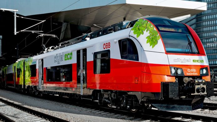
Siemens Mobility makes electric passenger trains. One of its latest orders is for 189 three-Car Desiro ML Cityjet trains for Austrian State Railways (ÖBB). These are electric multiple unit trains, designed to work from ÖBB’s 15kV 16 2/3Hz overhead AC supply.

It’s one of these units that’s particularly interesting. Taken straight off the production line, it has been constructed to incorporate Siemens Mobility’s ‘eco’ technology that will result in an EMU/battery bi-mode. Siemens has fitted a modular LTO battery system to the roof of the train, providing the unit with a range of 50km on batteries alone, with similar ‘off the wires’ performance to it running on AC power. The batteries can be recharged off the AC supply when running on the electrified line, topped up from regenerative braking, and can be fully recharged in as little as 12 minutes.

Battery technology

Lithium-ion batteries were first developed in the 1980s and have been used for mobile devices since the 1990s. On discharge, lithium ions move from the negative electrode (cathode) to the positive electrode (anode) through an electrolyte – the process is reversed on charging. They are quick to charge, have no memory effect (unlike nickel-cadmium batteries) and have a high energy density.

However, the electrolyte is flammable, and early fires caused problems for Samsung Galaxy Note 7 mobile phones and Boeing 787 airliners.

A development of the Li-ion battery, patented in 2001, is the NMC, which uses lithium nickel manganese cobalt oxide for the positive electrode in place of the lithium cobalt/iron/manganese oxides of early examples, with the negative electrode being graphite or another carbon-based material. Electric vehicles such as the Nissan Leaf use this battery technology.

More recently, LTO or lithium-titanate batteries use that material on the surface of their anodes in place of carbon. This allows electrons to enter and leave the electrode more quickly, permitting quicker recharges and giving longer life.

The Siemens X-EMU train uses these LTO battery cells.

The battery packs are part of a fully managed integrated, temperature-controlled system and it is anticipated that they will have a service life of at least 15 years – half of the expected life of the train. They will therefore need only one battery change in their lifetime. A similar arrangement using NMC batteries would typically require three or four changes throughout a train’s life and, although each NMC pack would be cheaper to purchase initially, the LTO battery has a significant advantage in terms of whole-life cost.

Fitting batteries to an EMU like this gives two possibilities. An X-EMU can run off the main electrified routes down an unelectrified branch line on batteries alone. For longer range ‘off-wire’ operation, a recharging station can be provided at the end-of-line terminus or even en-route.

In addition, the train can run through ‘extended neutral sections’ on a main line, electrified using a discontinuous electrification scheme without loss of performance. With this approach, railways could potentially be electrified at a significantly lower cost, resulting from the fact that difficult infrastructure (tunnels and bridges with inadequate clearance) would not be wired, instead relying on the train’s batteries for that portion of the route, with the batteries being recharged when the train reconnects to the AC supply.

The ÖBB Cityjet train completed homologation in August and entered passenger service on 2 September 2019 in the Linz area of Austria. Passengers throughout Austria will have the chance to ride on this exciting train in the coming months.

Elsewhere

Siemens Mobility’s ‘eco’ battery technology could also be fitted to a brand-new fleet of 20 Siemens Mireo trains (above) for Ortenau Network 8 in the German state of Baden-Württemberg, to operate both on and off electrified routes, giving the batteries ample time for recharging. The local government wanted an ‘emissions-free’ solution, so the electric/battery units could work well, but the contract award is currently under appeal by another bidder, meaning the award may not be confirmed as planned.

In the United Kingdom, where the more restricted loading gauge probably precludes the batteries being mounted on the roof, existing four-car units could be upgraded to include underfloor mounted Siemens Mobility ‘eco’ battery technology, increasing the potential of existing EMUs by turning them into battery EMU bi-modes.

Graeme Clark, head of business development for Siemens Mobility Rolling Stock in the UK, is keen to point out that, even when running on batteries, these are still electric trains. “Off-wire, they still have EMU acceleration,” he emphasised, “so they will have faster journey times than the diesels they replace, as well as being lighter, far more efficient and significantly cheaper to maintain.”

Improvements in technology are helping all the time. Electric regenerative systems can brake an electric train significantly and efficiently, with energy being returned for re-use to the infrastructure or (to recharge train battery systems), but friction brakes are still needed to bring it to a complete stop. As technology has advanced, the proportion of braking done electrically has increased, significantly reducing brake pad and disc wear and minimising maintenance cost.

The industry’s gradual move from asynchronous electric motors to permanent magnet motors will make a big difference in this area. They will be capable of braking the train to a complete stop, meaning that potentially, mechanical braking can be removed completely and replaced with a simple parking brake!

And there’s more

The other ‘clean’ fuel that’s much touted these days is hydrogen. Like electricity, its cleanliness depends on how it was made.

If it’s made by the ‘steam reformation’ of fossil fuels, particularly natural gas and methane, then significant quantities of both carbon monoxide (CO) and dioxide (CO2) are produced, so it’s not a zero-carbon process.

Some industrial processes produce hydrogen as a waste product. It wasn’t produced by a zero-carbon process, but it would otherwise be burned off and wasted, so using it to power trains is, essentially, recycling.

Then hydrogen can be produced by simply passing an electric current between two electrodes submerged in water. Oxygen comes off at one electrode, hydrogen at the other. There are no other waste products and no pollution.

Once again, the cleanliness of the electricity can be called into question, but if it comes from a wind turbine at 3am when the world is asleep and using very little electricity, then the power is both clean and essentially free, meaning that the hydrogen is also clean and is produced for only the infrastructure cost of the plant.

It can also come from nuclear power. EDF Energy R&D, in partnership with Lancaster University, Atkins, European Institute for Energy Research (EIFER) and EDF Group’s Hydrogen subsidiary Hynamics, is looking to design a hydrogen gas generation plant at Heysham power stations. The project, which is funded as part of the Department for Business, Energy and Industrial Strategy’s £20 million Hydrogen Supply programme, runs in two phases – the first is a feasibility study, which will be completed by September 2019, and the second (subject to selection by the UK government) will be the pilot demonstration, starting in 2020 and running for two years.

To use this ‘free’ hydrogen, Siemens, which makes both wind turbines and the electolysers that produce hydrogen, has designed the ‘eco’ concept to include an option for hydrogen fuel cells that will charge the batteries, giving extra range ‘off the wires’ or even allowing it to run on non-electrified long distance non-electrified routes.

Siemens is working with Canadian company Ballard, a market leader in fuel-cell production, to develop compact, lightweight high-power fuel cells that can be fitted easily onto trains. The fuel cells will recharge the batteries, which then power the train. This approach reduces noise, as the fuel cells are running under constant load, reduces hydrogen consumption and leads to longer fuel-cell life.

Will the future of passenger trains be overhead/battery/hydrogen hybrids? Quite possibly. The first Siemens ‘eco’ train powered by a hydrogen fuel cell will be on test in the near future and offers an excellent solution to the replacement of diesel trains and an alternative environmentally friendly approach to lines which could never justify electrification.

But all of this development leaves one unanswered question – what to do about freight trains? Here in the UK, the freight-only lines are not electrified, the trains are heavy, and batteries, with no overhead wires to recharge them, would not last long.

Is electrifying the whole network the only solution? Time will tell…


Thanks to Graeme Clark of Siemens Mobility and to Martyn Butlin and Andrew Cockroft of EDF for their help in preparing this article.

DfT (finally) publishes list of rail enhancement projects for CP6

The Department for Transport (DfT) has published a list of rail enhancement projects in its updated Rail Network Enhancements Pipeline (RNEP).

When it announced its funding of Network Rail in Control Period 6 (CP6 – 1 April 2019 to 31 March 2024), enhancements, other than those already underway, were not included.  In future, Network Rail would have to ‘bid’ for those and the DfT and Treasury would decide which ones to fund.

Provision was made in the CP6 settlement for funding to prepare the business cases and bids for enhancements, but it would not be a forgone conclusion that any particular scheme would be accepted and funded.

Pulling major projects out of the control period cycle would allow each one to be funded properly, with thorough planning, and so avoid the mistakes made on schemes such as Great Western Electrification when certain stages were rushed to hit CP deadlines, resulting in inadequate preparation and the ensuing cost and time overruns.

Rail Engineer looked at the new method of planning in March 2018, publishing a list of some of the candidate schemes for DfT finding for CP6.  Some of these were carry-overs from CP5 that would continue, others were developed during CP5 for implementation in CP6, while still more were just plans that would be fully developed after the start of CP6.

Despite that list, which came from Network Rail, the DfT has, until now, refused to confirm which projects were going ahead.  This caused some consternation amongst the supply chain, which wanted to ensure that skills and resources would be available when required.

There is therefore some relief that the DfT has now published its list of those favoured projects. Darren Caplan, chief executive of the Railway Industry Association (RIA), said: “This is a really positive development announced today by Transport Secretary Grant Shapps and we welcome this timely intervention at the Transport Select Committee.

“The Railway Industry Association and its members have been calling for a list of enhancements projects for well over a year, and that is why we launched our ‘Show Us the Rail Enhancements’ campaign in the autumn. So, it’s great news that the new Ministerial team has acted swiftly on taking office to deliver on this.

“This comprehensive list of enhancements will now give rail businesses some more confidence to plan, hire and invest in preparation for upcoming work. And it will help ensure we can get to work to build an enhanced world-class railway in the coming years. We and our members will now examine the list further, and work with the DfT and wider rail supply community to deliver these upgrade projects.”

Schemes go through four decision gateways before the funding is approved for Network Rail to deliver them:

Decision to Initiate takes the scheme into the pipeline and unlocks funding for a Strategic Outline Business Case (SOBC).

Decision to Develop builds on the SOBC and authorises development work towards a single viable option and to put together the Outline Business Case.

Decision to Design follows the Outline Business Case and permits technical development to ensure that the desired outputs can be delivered through the option being progressed.

Decision to Deliver passes the project over to Network Rail for implementation.

The DfT’s latest RNEP report includes the following projects under development:

Stage 1 – Determine

23 projects have passed the Decision to Initiate and are under development. Plans to provide a permanent solution to passenger congestion at Clapham Junction, for Wigan to Bolton Electrification and to improve capacity and performance on the Castlefield cross-Manchester Corridor are on this list.

Stage 2 – Develop

A further 22 projects are currently under development. These include the Western Rail Access to Heathrow, a new station at Cambridge South and the redevelopment of Euston Conventional Station.

Stage 3 – Design

A total of 13 projects are currently being designed with a view of taking them to the final DfT gateway of the Decision to Deliver. The Transpennine Route Upgrade falls into this category, as does East West Rail Phase 2.

Other schemes

If a scheme is entirely funded from other sources, it does not need to go through the RNEP process.  However, even if it is only part-funded by the DfT, it does.

And project that has already passed the decision to Deliver, which includes all the part-finished schemes from CP5, do not appear on the DfT’s list but are instead on Network Rail’s Enhancements Delivery Plan.

First light: The Riding Sunbeams trial of solar-powered electric traction

How many times have we looked at clever innovation and wondered why on earth no one thought of doing it before? Often the simplest of ideas seem to lead to the most elegant of engineering solutions. The truth is, of course, that invention is only half of the story. Sometimes the right meeting of minds must happen before a bright idea can become a reality.

To the best of our knowledge, the direct supply of solar power to rail traction systems has never been done, anywhere in the world. Now, thanks to a collaboration between Network Rail and a social enterprise scheme called Riding Sunbeams, the very first solar farm to directly supply power to trains has been switched on. That’s right, not in a distant country with a hot climate and wall to wall blue skies, but right here in our cloudy UK, near Aldershot station to be precise. The new system went live on 23 August.

Riding Sunbeams is a joint venture between 10:10 Climate Action and Community Energy South. 10:10 is a registered charity on a mission to speed up action on climate change by inspiring more people to become involved, while Community Energy South was set up in 2013 as an umbrella organisation, enabling community organisations and local energy groups to grow as sustainable low carbon businesses.

Installing solar panels. (photo by Andy Aitchison / 1010 Climate Action)

Feasible

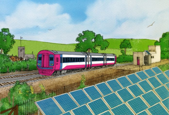
Behind the Riding Sunbeams project is a pretty simple idea. It is that solar farms could be installed next to the train tracks – on embankments, train sheds, nearby fields and industrial buildings – and that these could power the railway directly to provide traction power for the trains.

In 2017, the 10:10 charity brought together experts from the Energy Futures Lab at Imperial College London, Community Energy South and electrical engineering specialists Turbo Power Systems, to find out whether the idea was feasible, and the answer was yes. It was estimated that solar traction power could realistically provide around 10 per cent of the energy needed to power trains on the UK’s 750V DC electrified routes.

Community energy, where local people own the renewable energy and benefit from it, is at the heart of this work. Riding Sunbeams has a mission to see community and commuter-owned solar farms powering the railways for the mutual benefit of the railway routes, the communities that host them and, of course, the planet. In other words, to have third-party funding contributing to the national rail network. This is no madcap scheme; the idea has huge potential for metros, trams and heavy rail in the UK and around the world.

Finishing touches. (photo by Andy Aitchison / 1010 Climate Action)

Benefits

Network Rail purchases an awful lot of electricity. The potential to obtain even 10 per cent of the DC third rail electrified network’s energy requirements from renewable sources, and at a cheaper rate, was worthy of consideration.

Stuart Kistruck is Network Rail’s director asset management for the Wessex route. In 2017, he had attended a presentation by Riding Sunbeams. “Making use of solar energy, produced on our own land, seemed like such an obvious thing to do,” he said.

“We started conversations and it became clear that the third-rail electrified Wessex route could provide favourable locations to trial the technology. We have many southerly facing cuttings that could be used for solar farms, which would not only provide some of our energy needs, but also relieve some of our commitments to vegetation management.”

Stuart also saw that community energy, where local people own the renewable energy and benefit from it, could be at the heart of such a scheme. “There is clearly an opportunity for community-energy funding to benefit the railway – connecting solar farms, not necessarily on railway land, to the rail network.”

The Riding Sunbeams’ ‘First Light’ demonstrator project has attracted funding from Innovate UK and the Department for Transport. Six potential sites for the trial were identified across the Wessex route, with a location near to Aldershot station being the one chosen for the pilot scheme. It offered a suitable area of waste land for the solar farm that was conveniently close to an existing traction power supply point (substation).

Ready to power a train. (photo by Andy Aitchison / 1010 Climate Action)

Compatible

In terms of power transmission efficiency, the relatively low traction voltage of 750V does not lend itself to distribution over long distances. For that reason, it is necessary to provide third-rail traction supply points every three to five kilometres along the railway.

It was realised that it would be possible to connect solar farms into the existing 33kV AC feeder systems that carry power from the grid supply points (GSPs) to the substations. Although this approach will lead to some DC-AC-DC conversion losses, it has some practical advantages over DC-DC supply to the substations:

Equipment for connecting solar farms to high-voltage AC networks is very well established and widely available. Being able to make use of existing technology (usually used for something else) for deployment on the railways has reduced the development time from an estimated five years to about one year.

Connecting to the feeders helps to overcome the major technical challenge for solar traction power: intermittency. This is because each GSP supplies around ten to fifteen substations. The load is shared across all of these, creating a more stable demand than if only one substation were to be fed. It may also be possible to export small amounts of surplus power from the feeders back onto the grid via the GSP.

This approach should largely negate the possibility of DC voltage-range exceedances and other power quality issues on the tracks, which would have increased operational risk.

Challenges

Despite the compatibility of the technology, which makes it straightforward to bolt the new equipment onto existing traction substations, Leo Murray, director of innovation for 10:10 Climate Action, explained that there are still technological challenges: “By its nature, the supply is intermittent and we have a very peaky load. And of course, the periods of peak demand and peak generation don’t coincide.”

Depending on the nature of the rail traffic, there can be long periods with no demand interspersed with periods of high demand. Leo continued: “A train under acceleration may draw up to 2,000 Amps. Lineside storage (batteries) could provide a solution, but the required technology for rail systems is not developed. We would be faced with perhaps a five-year development programme, which couldn’t pay for itself.

“Even in the long term, the business case for using battery storage doesn’t look as good.”

This was another reason for choosing the Aldershot substation for the trial. The location should provide a reasonably constant load.

The Aldershot trial site.

The Aldershot trial is a modest undertaking with a solar array that comprises just 135 panels, installed for Riding Sunbeams by local firm Basingstoke Energy Services Cooperative. Peak output is rated at 37 kW. Its purpose is purely to test the technology and the modelling that was used as part of the feasibility study.

Theoretical modelling of the systems was undertaken by Dr Nathaniel Bottrell, then with Imperial College. He has since joined Ricardo Energy & Environment as a consultant, and this company has itself become an important partner in the scheme.

Design work on the ‘First Light’ solar traction test unit was completed by Riding Sunbeam’s resident engineer Ernie Shelton, in dialogue with Network Rail’s Wessex Route’s lead traction engineer Nigel Wheeler – Network Rail effectively acted as the DC-traction engineering consultants.

As Leo put it: “The objective at Aldershot is to test the technology without spending millions of pounds.”

Data loggers would monitor the load, generation capacity and the quality of the supply.

Support

Meanwhile, Network Rail is, of course, looking closely at the system performance and ensuring compliance with its own technical requirements for safe operation. These include protection settings and the fail-safe operation of circuit breakers in the event of a fault condition.

The quality of the supply is also under scrutiny, with the production of voltage spikes and harmonics being closely assessed. The potential for over-supply during periods of low demand and peak generation is another concern, but Stuart Kistruck is keen to stress that, overall, the position of Network Rail is one of collaboration and support.

There is also involvement from the electrical engineering department of Birmingham University. Using data gathered from the Aldershot installation, and from data loggers at the other five proposed sites, they will undertake sophisticated modelling. By pinning this to Network Rail’s traction model, it should be possible to predict accurately how a larger solar installation should perform. This work will be important in ensuring that a successful and commercially viable engineering solution is attained.

The trial underway. (photo by Andy Aitchison / 1010 Climate Action)

Expansion

Assuming all goes well, by this time next year, the other five sites that have been allocated for trials on the Wessex route should be happily generating electricity for the third rail system. The trial itself is open-ended with no fixed timescale, but Riding Sunbeams has great ambition.

Leo Murray explained: “Once the technology is proven, we’ll go bigger, offering shares in solar farms to communities and commuters, so that local people will own and benefit from the clean energy powering their trains.”

There is no doubting the magnitude of the opportunities that lie ahead.

Leo continued: “We’ll be gathering electricity demand data from our six potential solar sites in the south of England. Putting this real-world data together, we’ll be able to work out how to plug in much larger solar arrays to power trains in future.”

It’s estimated that those arrays would each be capable of generating between one and four megawatts. All being well, the world’s first ever full-scale, community and commuter owned solar traction farm should be connected to the railway during 2020.

Overhead

As we have seen, the generation of electricity using solar technology lends itself to supplying trains on the 750V DC third rail system. Looking ahead, though, Riding Sunbeams is working with Transport for Wales to build renewable energy into their plans to electrify the lines north of Cardiff using 25kV AC overhead line equipment (OLE).

The difficulty with retro-fitting existing 25kV AC lines with solar power generation is that the OLE feed points tend to be much further apart than on DC lines. They also tap directly into the national transmission grid, rather than distribution. This means that, even if a solar farm could be sited nearby, bespoke equipment would be needed in order to provide an interface.

An alternative would be to build new feed points near the solar farms, but this would create disruption to rail services.

Either way, the costs involved are higher, and the specialist equipment needed for feeding the OLE at 25kV would require development and approval.

That said, by taking account of solar-power generation at the design stage, the South Wales Green Valleys scheme should be able to accommodate new feeder substations close to the best sites for solar farms. Leo is enthusiastic about this, and about other possibilities too: “We’ll also be looking at the potential to use community wind turbines to power the trains.” There is currently a ban on new land-based wind farms in England, but not in Wales.

Unlocked

Back at Aldershot, if successful, the Riding Sunbeams: First Light project will prove that direct solar PV supply can be successfully integrated into UK railways without negatively impacting on rail operations or safety.

This is a world first and it should also establish the business case and contractual relationships needed to unlock opportunities for community energy groups and other renewable generators. It is as much about developing innovative ways of owning and financing renewable energy as it is about proving the technology.

The rail industry plays an important role in reducing carbon emissions and, as part of that, Network Rail is committed to making use of renewable energy. The necessary land is available, the technology exists and there is the will to take this exciting project forward. With the passing of net zero emissions legislation in the UK there has never been a better time for Riding Sunbeams to help the rail industry respond to this challenge.

To quote Riding Sunbeams, it’s time to get on board – here comes the sun!

HS2 way out in front in tunnel design for high-speed rail

Now, what are the similarities between Cyrano de Bergerac, the central character in the 1897 play of the same name by Edmond Rostand and a modern Japanese high-speed train?

Perhaps they’ve both got panache. Cyrano de Bergerac did indeed have panache, Rostand having introduced that very word into the English language. Undoubtedly, the Japanese train also has panache – or panasshu.

What else? They both have very long noses, but whereas Cyrano de Bergerac was born with a long nose, the Japanese high-speed train had its nose specially designed – and designed for a very specific purpose.

The train has to travel very fast.

A typical Shinkansen train showing its long nose. (DAJF)

But there’s a problem here. Take a look at the latest images of the trains proposed for HS2. They too have to travel very fast – just as fast as, if not faster than, their Japanese counterparts. The HS2 trains also have panache, but their noses are far more ‘Audrey Hepburn’ in comparison. So, what is going on? Why have the very savvy Japanese embarked on such prominent nose jobs whilst the Brits are so nasally understated?

The basic reason is because HS2 will be tailoring new rolling stock to suit its new infrastructure, while the Japanese have had to tailor new rolling stock to suit existing infrastructure.

A bit of background

The Shinkansen  railway was a ground breaking achievement. Opened in 1964, in time for the Tokyo Olympics, it took high speed rail travel to a new level. Speeds of 210km/h in commercial passenger service had not been seen anywhere in the world.

Everything was new – both the rolling stock and the infrastructure and, as it turned out, the aerodynamic effects. The trains were streamlined to minimise drag in the open air and through the (many) tunnels, which were conventional tubes through the ground.

When the railway was extended in the 1970s, those living near the portals of one of the new tunnels were disturbed by loud bangs that occurred a short while before a train emerged. Technically, these are known as micro-pressure waves. To the press, they quickly became known as ‘sonic booms’. Something had to be done.

The German solution. West portal of the Finne tunnel, designed for 300km/h, built 2011 and opened for service 2015. Note the smaller number of larger slots compared with the HS2 design for 360km/h running.

Tunnel hoods

The engineers quickly analysed the problem and realised that they had to slow down the build-up of pressure in front of the train before it entered the tunnel mouth. To do so, they designed and retro-fitted hoods for the tunnel portals that would guide the air as the train entered. Without these measures, the pressure wave would build up too quickly and, after travelling down the tunnel bore at the speed of sound, would emerge at the other end.

The world learnt from the Japanese experience and just about all of the long tunnels on subsequent lines have been fitted with hoods of one pattern or another.

As a result of this experience, sonic booms are something that designers of all high-speed lines are mandated to avoid. This, of course, includes HS2.

The German solution. South portal of Blessberg tunnel on the Nuremberg-Erfurt line which was completed in 2014.

360km/h maximum speed

As HS2 chief engineer Mark Howard is keen to point out: “We don’t want to find there’s a problem only when the first trains start to run.”

Having an iron grip on all aspects of the project specification will ensure that the problems encountered on the Nuremberg-Munich high-speed railway in Germany will not occur.

The emission of micro-pressure waves depends on both tunnel length and on the effects of friction. A design change from ballasted track to slab track inside two of the longer tunnels, Euerwang (7,700 metres) and Irlahüll (7,260 metres), reduced the surface friction and led to sonic booms occurring near the portals of both tunnels. Measures had to be taken to stop this phenomenon before the line could open in 2006, and acoustic absorber panels were fitted between the rails.

High speed lines that have been built to date have, in broad terms, a maximum line speed of up to 320km/h. HS2 is being designed to run at a maximum of 360km/h. On the face of it, this may not seem to be a significant speed increase – just 12½ per cent.

However, the physics of micro-pressure wave propagation is such that they increase in proportion to the cube of the speed – and by more than the cube in longer tunnels. A quick calculation suggests that the relatively modest 40km/h increase in speed leads to at least a 42 per cent increase in effect. Mitigating this would be way in excess of the capability of existing tunnel hood designs and so a new solution is required – one that has to be carefully calculated, modelled, designed – and verified.

The University of Birmingham’s high-speed test track at Derby.

Model trains at (really) high speed

As we covered in a Rail Engineer article back in issue 160 (February 2018), Arup and Birmingham University are at the forefront of tunnel aerodynamic research, using a mix of scale model testing and computer modelling to verify and optimise tunnel designs. The university’s scale model test-rig catapults model trains down a 150-metre-long track in a huge shed at British Rail’s former research centre in Derby. Scale models of the tunnel and hood are placed over the track to measure the performance of the proposed design.

A 1/25 scale model as used on the Derby test track.

Whilst it is possible to make train and tunnel models to 1/25 scale, it is not possible to scale down our atmosphere or its physical properties. However small the model trains, speed through the air has to be full-scale if the results are to read across directly to the full-scale tunnel. The catapult isn’t quite powerful enough to manage 360km/h – but it is still blink-and-you-miss-it fast, and plenty fast enough to see that, in principle, the design works as intended.

The scale model results are used as test-cases for validating the computer models, and then the computer model is cranked up to the full 360km/h. Finally, the details of the hood can be tweaked in the computer model to optimise the design to make it as cost-effective as possible whilst meeting all the numerical targets.

Leading the team is Richard Sturt, an Arup Fellow whom we met during the preparation of our previous article. Richard has considerable experience in the application of fundamental physics to engineering problems, along with knowledge of the strengths and weaknesses of computer modelling.

“HS2 will have hoods that are longer than in Germany or Japan because of our higher speeds and tight tunnels,” he explained. “To make a really efficient design, we’ve used an idea by Prof Alan Vardy (one of the world’s leading academic experts in the field) to shape the hood so that it smoothly narrows down from quite a big entrance to meet the main tunnel without any sudden changes of cross-sectional area.

“Then there are many small holes along the length of the hood which let the pressure out in a very controlled way, so dissipating it very smoothly, without any sudden changes.”

Comparison of the HS2 design of tapered portal for 360km/h and an earlier 300km/h version.

Standards – or lack of them

There is a difference between the treatment of micro-pressure waves and pressures experienced on a train by passengers. As Mark explained: “The standards for passengers inside the train are designed to give a backstop if a window were to break, so exposing passengers to the pressure outside. That would be very much worse than the normal operating scenario when they’re seated in a nice comfortable train.

“Standards apply to the emergency rather than the normal condition. Mandatory requirements are in the standards for interoperability.

“Nothing covers the micro-pressure waves.”

Noise levels generated by HS2 are embedded in the Act of Parliament that authorised the project, but this is wheel/rail/aerodynamic noise arising from the running of trains. Despite there being hundreds of papers written on the subject of micro-pressure waves at tunnel portals, there is practically nothing that defines the levels that are acceptable. What constitutes a nuisance in some circumstances will be benign in other cases. An audible thump at the dead of night in rural surroundings will cause many more issues than one in an industrial estate.

This vexed problem has been researched in Japan and resulted in a rule of thumb – what people find tolerable and what not. Rules in Germany are based on measurements made on a sound meter.

Impression of an HS2 tunnel portal showing the row of slots that form part of the shock prevention design.

Eliminating the problem

Given the dilemma of ‘guessing’ what noise level would be acceptable, Mark’s team made the decision to opt for a design that eliminated the noise altogether – or at least to sound frequencies below the capability of the human ear. The HS2 designs will give rise to pressure changes that may well be detectable using instrumentation, but nothing will emerge into the open air that will be within the audible range.

All this explains the difference in approach by the Brits and the Japanese to train design. The physics of sonic booms is the same wherever you are on the planet. It’s just that HS2 has the opportunity of designing and building new tunnel hoods to avoid the pressure build-up with speeds of 360km/h. A 100-metre tunnel hood is relatively straightforward to build.

Alternative styles of portal for varying applications.

The Japanese started early with their high-speed lines and so their infrastructure is, by and large, fixed. They had little alternative but to change the trains.

As stated earlier, the micro-pressure wave effects increase by the cube of the speed and so, if there’s little hope of altering the tunnel hoods, then it’s down to the front of the trains to do their part. But the effect is also dependant on the length of the nose, which is why the newest, and fastest, Japanese trains have the longest noses. Ramp up the speed to 360km/h, and the nose would need to be too long to manage.

Sorry Cyrano!

Denmark’s first high speed line opens

Vectrons will replace these DSB ME diesel 1531 leaves Roskilde. (Keith Fender)


Guest writer: Keith Fender

On 31 May, Danish Crown Prince Frederik officially opened the first section of 250km/h high-speed line in Denmark between the suburbs of Copenhagen and Ringsted to the south west – free public services on the new line operated later that day.

Initially, the 60km long line will not be used as a truly high-speed line. No operator in Denmark has trains capable of operation at 250km/h and an interim signaling system, installed by national infrastructure manager Banedanmark, will limit traffic to 180km/h until ERTMS is in use.

The new line has cost €1.6 billion, mostly funded by the Danish government (98 per cent) with the EU, via its TEN-T Programme, contributing the remaining two per cent.

More capacity and faster journeys

Successive Danish governments have set the political goal of cutting travel time across the country whilst also reducing carbon emissions. They have aimed to achieve this, in part, by investing in major rail infrastructure projects including large-scale electrification and the introduction of ERTMS with ETCS Level 2 signalling.

Funding for these projects has been provided via a number of different sources, controlled by central government. The DKr28.5 billion (£3.3 billion) Togfonden DK (Train fund Denmark) infrastructure package, announced in 2013, established by government using tax revenue from Denmark’s oil and gas industry, was originally envisaged as sufficient to fund nationwide electrification plus several new and improved lines.

Reductions in oil prices (and consequent tax revenue reductions) have led to the fund and its plans being scaled back. As a consequence, the new Copenhagen to Ringsted line, ETCS deployment and other works in connection with the new Fehmarnbelt Fixed Link tunnels (connecting Denmark to Germany under the Baltic Sea) are being funded separately.

Planning for the new line

Danish rail infrastructure manager Banedanmark is a governmental body under the Ministry of Transport, Building and Housing and acts as the national rail infrastructure manager, although some regional lines have other owners. Banedanmark is responsible for main-line electrification, installation of the ETCS signalling system and has led the construction of the high-speed line from Copenhagen to Ringsted.

The main purpose of the 60km long high-speed line is to increase capacity for east-west domestic services from Copenhagen to Odense and, beyond, to towns and cities in Jutland. Before the new line opened, all main line services to western Denmark, plus those heading south to Germany, used the existing Copenhagen to Ringsted line, which is saturated at peak times as the section in the Copenhagen suburbs is just double track.

bi-mode train, Danish-style. A three-car IC3 DMU leads a four-car IR4 EMU with pantograph up.

The existing major junction station at Roskilde (where lines south to Nykøbing Falster and the Rødby – Puttgarden train ferry to Germany, plus those southwest to Ringsted and Odense, diverge) is already operating at maximum capacity at busy times with frequent passenger services (mostly domestic) sharing the route with freight services connecting, not only Copenhagen, but also Sweden and Norway, with Germany and the rest of Europe. The new line provides additional capacity and a diversionary route in the event that the classic line is closed.

Looking forward, the new Copenhagen to Ringsted line is the first part of new rail infrastructure that will connect Copenhagen with the new international undersea tunnels under the Fehmarnbelt, which, when complete in around a decade, will substantially reduce journey times between Danish cities and those in Germany.

The new 18km long Fehmarnbelt fixed link, which is currently expected to be completed in 2028, will be built using prefabricated immersed concrete sections. These will comprise a double track electrified railway plus a four-lane motorway.

In 2028, travel time between Copenhagen and Hamburg will be approximately 2.5 hours by through electric train. That is almost half of the current travel time on a route that, today, has to include either the Rødby to Puttgarden train ferry across Fehmarnbelt or a much longer land route in both Germany and Denmark.

Banedanmark’s separate Ringsted – Fehmarn (Rødby) project will also upgrade the line from Ringsted to Rødby Færge to serve the new tunnel. Once complete, the line will be electrified and rebuilt for 200km/h operation with ETCS Level 2 signalling. The upgrade will be carried out in stages, commencing with the section between Ringsted and Nykøbing Falster by 2023 and with the last stage from Nykøbing Falster to Rødby Færge completed before the opening of the Fehmarnbelt Link.

The high-speed line project had been under discussion since the early 1990s, with multiple options considered, and was finally approved on 26 May 2010 when the Danish Parliament passed the Construction Act. The project was planned and developed by the former Danish Traffic Authority and, in 2010, handed over to Banedanmark which established a separate Copenhagen-Ringsted project business unit to deliver the new high-speed line.

Between 2010 and 2013. preparatory works, including utility relocation, archaeological surveys and site access routes, were undertaken.

Most freight trains are already electrically powered, such as this DB Class 185 seen hauling an intermodal train at Roskilde in April 2015.

The new line

The new electrified double-track line has been built entirely to the south of the existing Copenhagen to Ringsted (via Valby and Roskilde) line and uses a different route between Copenhagen main station and Ny Ellebjerg. This creates capacity on the classic route via Valby, where the mainline is double track all the way to Taastrup in the western suburbs of the city. The other pair of tracks paralleling the classic route are electrified at 1.65kV DC and reserved for S-Tog (suburban train) use.

The new line has reduced the overall Copenhagen to Ringsted distance by just over a kilometre to 61.7km. When operating at full design speed, it will also significantly reduce journey times.

Full scale construction began in 2013 and was completed on time by early 2017. From Copenhagen, the new line starts at Ny Ellebjerg on the existing secondary line to Køge but at a lower level, forming a junction with the line from Copenhagen Kastrup Airport (and Sweden).

The line is built using conventional ballasted track and electrified at 25kV AC, which is used for all mainline electrification in Denmark. Tracklaying began in late October 2016 and was completed in the beginning of February 2017. From April 2017, the completed railway line was electrified and signalling was installed.

A joint venture of Atkins, Vössing, EKJ and Sweco delivered the DKr200 million (£27 million) railway technical contract for Banedanmark. As part of this, Banedanmark developed a new design for high-speed track switches in conjunction with BWG/Vossloh to provide greater comfort for passengers.In response to Banedanmark’s requirements, Atkins completed all designs and as-built documentation for the railway in one integrated 3D-model, so as to prevent any physical conflicts and facilitate the work of all contractors.

The new line has few major structures, most of those which have been built are to enable it to pass under or over the motorways that the new line has largely been built alongside. The line initially follows the M21 motorway before crossing a major motorway junction on a bridge and then heading southwest to Køge, running some distance west of the E20 motorway and largely parallel with it all the way from Mosede to Ringsted.

During construction, a temporary section of motorway was built to enable railway construction where the line crossed the M21 motorway south of Copenhagen – the resulting 800 metres of diverted motorway enabled Banedanmark’s contractors to work without any disturbance, from June 2014 to September 2015, whilst they constructed the tunnel the new railway uses to pass under the motorway.

Temporary motorway built to enable railway construction where the line crossed the M21 motorway south of Copenhagen.

Banedanmark estimates that this approach reduced overall construction time by 18 months and minimised disruption to road users during the period. Once the tunnel and track bed were complete, the motorway was reinstated in its original place above the new railway.

Where the new line crosses one of Denmark’s busiest motorway junctions at Vallensbæk, a 512-metre-long railway bridge has been built across the junction, with the work being done in 2014-2016. Although it spans the entire junction, the motorway was only partly closed (once in each direction) for two weekends whilst the bridge steelwork was lifted into place.

New stations

The only brand-new station is at Køge Nord, which is a park and ride station on the northern fringe of the town of Køge. In addition, a new S-Tog/Copenhagen Metro interchange station has been provided at Ny Ellebjerg, where the existing station has been rebuilt and expanded to serve the new line.

Køge Nord, which is designed as a park and ride station on the northern edge of the coastal town of Køge, has been built where the existing Copenhagen – Køge S-Tog line runs parallel to the new line and just north of the recently electrified Roskilde to Køge / Næstved secondary line, to which a connection has been built via a flying junction just south of Køge Nord. Electrification of this line between Køge Nord and Næstved has recently been completed, allowing electric trains using the new line to serve Næstved.

A new pedestrian bridge was built at Køge Nord station. 225 metres long, it turned out to be one of the project’s most complex construction tasks. It spans both the motorway and two railway lines (the new one and the S-Tog route). The engineers responsible for actually building it were working to a design that had been selected at the planning stage.

Køge Nord station from the air looking north in 2018. The centre pair of the four tracks nearest camera are the new highspeed line through lines (the outside tracks are the connections to the existing Roskilde to Køge line. The Copenhagen – Køge DC electrified S-Tog line is on far right on the other side of the motorway. The new 225-metre footbridge crosses both railways and the motorway.

The key issue was to find an engineering solution for the ribbed roof in the slight curves of the bridge which both complied with the aesthetic appearance in the design brief but also would protect pedestrians in torrential rain (not uncommon as Køge is only a few kms from the Baltic).

Detailed design work was only completed in Spring 2017 and the sections of the bridge were lifted into place between November 2017 and August 2018. It was completed in May 2019.

Commissioning and initial operations

Commissioning work began in August 2018 when the overhead power supply was switched on and test running began to prove the line at its design speed. As it is the country’s first high-speed line, a new national rail speed record was set during the high-speed test trials, which took place from 22 October to 7 December. The new speed record is 255.6km/h set by a Eurosprinter loco from Hector Rail.

In late 2017, Banedanmark issued revised plans delaying the implementation of the nationwide ERTMS level 2, baseline 3 deployment by seven years from 2023 to 2030. The reasons for this change were largely rolling stock driven – problems obtaining and fitting onboard equipment to much of the DSB legacy, long-distance DMU fleet (IC3 and IC4 trains) was a key reason for the change. Some other DSB and Arriva fleets are being/have been equipped more quickly.

Danish national passenger operator DSB currently has 26 Vectron electric locomotives, capable of 200km/h running, on order from Siemens and due to be delivered from 2021. It is also is tendering for at least 100 new EMUs for delivery in the early 2020s. All the new trains will be ERTMS equipped.

The interim signalling system is based on a track vacancy detection system from Siemens and uses conventional line block signals/ATC. The 60km line is divided into five block sections with reversible signalling.

Under the temporary signalling system, the maximum speed is limited to 180km/h, which allows five trains per hour in each direction. Implementation of this system led to the new opening date of 31 May 2019 (instead of 9 December 2018 as originally planned).

All the necessary ERTMS hardware for ETCS Level 2 operation is installed on the new line but will not be used to replace the temporary ATC system until sufficient trains equipped with it are available.

Test train on the new line 25 October 2018 – Hector Rail Eurosprinter 242 502 is on rear of DB Systemtechnik test train.

Operation

From June, only one or two trains an hour are using the new line, but traffic will increase progressively with more trains by the December timetable. The majority of these passenger trains will be diesel-powered in the first few years, for the simple reason that Danish national operator DSB has not yet obtained new fleets of electric trains. The line is designed to be used by any TSI compliant passenger or freight train, potentially enabling existing German or Swedish multi-voltage ICE or X2000 trains and Traxx/ Vectron locos to use the line.

Perhaps uniquely in Europe, Banedanmark will charge the same track access charges on the new line as on the existing route.

The new line is designed for mixed traffic, although freight will not use it until 2021 at the earliest. Maximum axle loading for the new line is 25 tonnes, however this is higher than the existing lines at each end, which each have a 22.5 tonne maximum. Passing loops capable of handling Danish standard 835-metre-long freight trains have been built at Lellinge, three kilometres east of Køge Nord station, to allow passenger trains to overtake freight.

Banedanmark, with contractors, are currently completing the new high-speed line’s connections with the existing railway at both Ringsted, where a flat junction is now planned, and Vigerslev in the suburbs of Copenhagen, where a flyover enables trains from Sweden towards the classic line (via Roskilde) to cross the new line without pathing conflicts.

Future plans

Banedanmark expects that traffic will grow over the first few years. Its full potential is likely to be realised from the mid-2020s, by which time ETCS deployment will be very widespread and DSB will have replaced many of its older diesel trains with new electric ones.

Freight use of the new line (almost all of which is now electrically powered) will probably start from 2021. From 2030, the Ringsted – Fehmarn (upgraded) line, plus the opening of the Fehmarn Belt link and completion of the ETCS rollout, will lead to much more traffic, significantly reducing journey times to towns and cities south of Copenhagen as well as to Hamburg and other German cities.

Banedanmark began work to upgrade the line west from Ringsted in March 2019 as far as the Great Belt (Storebælt) crossing at Korsør. The upgrade will be completed in two stages; 2019-2020 and 2022-2024. The line is heavily used and currently suffers from temporary speed restrictions in several places where infrastructure renewal is required.

Two further sections of new high-speed lines are proposed, but not yet funded, west of Ringsted – a 35km stretch of the line to Odense on the island of Funen and 24km south of Aarhus on Jutland. Both will be constructed for at least 200 kph.


Thanks to Banedanmark for helping to prepare this article.

Zero-carbon: the need for innovative construction plant


Guest writer: Simon Meades, Ecolite product manager at Taylor Construction Plant.

With the announcement this year that the UK has become the first major economy in the world to pass laws to end its contribution to global warming by 2050, the pressure is now on to bring all greenhouse gas emissions to net zero. This means good practice of energy management on site. Consequently, the efficient use of construction plant equipment powered by sustainable fuel has never been so important.

This creates a huge opportunity for plant hire companies to expand their fleet and offer customers cleaner air products and services. It also opens the market for new, innovative plant equipment that produces zero harmful emissions.

There are many solutions already available, some of which are currently being used or trialled by the rail construction industry, but which ones are best is still to be proven. Working off-grid is perhaps the biggest challenge, as connecting to the National Grid could dramatically reduce CO2 emissions, instead of using diesel generators, which produce not only air pollution but also noise.

Typically, nearly everything on site is run by generators – from light towers, CCTV, welfare cabins and power tools – so imagine the reduction in pollution if everything could be run by an alternative power source in the absence of mains electricity. Hybrid generators are one option, as they use battery and solar power to reduce the run time of the generator; diesel is only used to supplement the battery for high-power jobs or to charge the batteries.

The clean alternative

Another option is a hydrogen fuel cell/battery hybrid generator, which is completely free of diesel.

A hydrogen fuel cell generator produces electric power by combining hydrogen with atmospheric oxygen. The only emission from these cells is water vapour, and they are virtually silent in operation, which is a big advantage when complying with Section 61 of the Control of Pollution Act. With zero impact on air pollution levels at point of delivery, zero noise pollution and no risk of fuel spill, hydrogen fuel-cell power arguably presents the perfect solution for a healthier work environment.

This could be why we are increasingly seeing hydrogen fuel cells in our cities. London now boasts entirely hydrogen-powered bus routes, and many cities and motorways are installing the vital fuelling stations needed to allow wider adoption of hydrogen vehicles. Britain also has its first hydrogen fuel cell train, the ‘HydroFLEX’, being developed by Birmingham University and Porterbrook, which presents a much greener solution than bi-mode trains which run off electricity where there are overhead cables, and off diesel the rest of the time.

Hydrogen fuel cells offer greater efficiency as, with a continuous supply of hydrogen, a fuel cell can provide electrical energy indefinitely, unlike a battery which requires charging or replacing. It is also more reliable than trying to use sun or wind to generate a constant flow of energy. However, hydrogen fuel cells can be hybridised with these renewable energies to further improve efficiencies – making this technology very versatile. For example, a hydrogen fuel generator with battery power and PV (photovoltaic) solar panels can effectively provide sufficient energy to power a welfare cabin.

So, when it comes to reducing carbon emissions for railway construction and maintenance, hydrogen fuel cell/battery generators could help provide a sustainable solution for reaching net zero. This technology is already being used by several major rail infrastructure companies with great success, not only to reduce carbon emissions but also to cut noise pollution when working near residential properties.

Low noise, low pollution

A good example of this was the railway enhancement work which took place in the Oxford area last year. Working 24/7, and in close proximity to residential properties, the Network Rail Western Enhancement Delivery (WED) team knew it had to make every effort to keep noise down to a minimum.

It was therefore recommended that Network Rail needed the TCP Ecolite TH200, which would give them a 200W LED output and longer run times. This hydrogen fuel cell light tower, which is virtually silent in operation, would also help WED to reduce noise pollution within the residential area whilst work was being carried out at night over a five-week period.

TCP and Torrent Trackside provided Network Rail with 25 portable Ecolite TH200 hydrogen fuel cell light towers, which were positioned at various site locations along the Oxford corridor. Collectively, the units, which have been designed to carry four cylinders of hydrogen gas, delivered an average of seven hours of LED light each working night over a five-week period.

During the project, 122 cylinders of hydrogen gas were used, providing a total energy saving of over 19,000kWh and a significant reduction of CO2, when compared to a modern diesel light-tower. The lights not only reduced disturbance to residents, but also reduced the carbon footprint throughout these intensive works.

Having equipment that is fuel efficient helps reduce vehicle movements, which again contributes to lowering the carbon footprint, as does having smart remote monitoring to control the run time of products during periods of peak and low activity.

This is undoubtedly an exciting time for manufacturers of plant equipment as the demand for zero-emission decarbonising products can only increase if we are to reach net zero by 2050.

BIM on the Northern Line extension

London Underground’s Northern line extension, which is being built from Kennington to Battersea with a new intermediate station at Nine Elms, uses Building Information Modelling (BIM) as the basis of its design and documentation. This requires LU to put the same level of rigour and governance into creating and managing information about infrastructure assets, as it does in building and operating the assets themselves.

BIM is a process involving the collaborative production, use and management of digital representations of the physical and functional characteristics of a facility or asset. The resulting information models, when fully coordinated, provide a shared knowledge resource to support decision-making about a facility or asset throughout its life – from early concept stages, through increasing detailed design, construction, operation and maintenance, and ultimately decommissioning, removal and demolition.

The objective of BIM is to procure/produce, manage and maintain data and information about engineered assets that are complete, consistent and trustworthy for use across operational and business intelligence purposes. This aims to drive efficiencies in the production, modification, operation and decommissioning of engineered assets, through data analysis that helps improve decision making to deliver best value to stakeholders.

BIM is a collaborative process that leads to better solutions for clients and their supply chains by enabling lean, accurate and complete design information for an effective construction process and leaves clients with better tools for asset management. Assurance is at the heart of BIM and, arguably, its most important use.

Telecoms and BIM

As part of its work on the Northern line extension, telecommunications systems integration specialist ADComms, a Panasonic company, has been implementing BIM within the business through both the design and construction phases and is working towards Level 2 BIM compliance. This will ensure that the company creates and shares appropriate information, in a suitable format, at the right time to facilitate better decisions throughout the delivery and operation of a built asset.

ADComms is currently committed to updating its current ISO 9001 suite of quality management documentation to incorporate BIM for integrated project delivery design, CDM, safety planning, and assurance.

On the Northern line extension, this will contribute to LU’s duty to deliver design, construction and maintenance/operations handover information (both graphical and non-graphical), in line with the April 2016 mandate from Government that all UK public infrastructure projects meet BIM maturity Level 2.

Carl Pocknell, ADComms managing director, commented: “BIM is not the future, it is now – a day-to-day reality. With the advances in communications technology being developed under Industry 4.0, this is an opportunity to engage and develop holistic, collaborative, digital approaches and methodology workflows and realise tangible benefits for our clients and their end users.

“Once BIM adoption has been agreed, then BIM must become the norm.”